Cathode-ray tube display device
A technology of cathode ray tube and display device, which is applied in the direction of cathode ray tube indicator, cathode ray tube/electron beam tube, electrode device and related components, etc., can solve the problems of obvious image noise and large image noise, etc.
- Summary
- Abstract
- Description
- Claims
- Application Information
AI Technical Summary
Problems solved by technology
Method used
Image
Examples
Embodiment 1
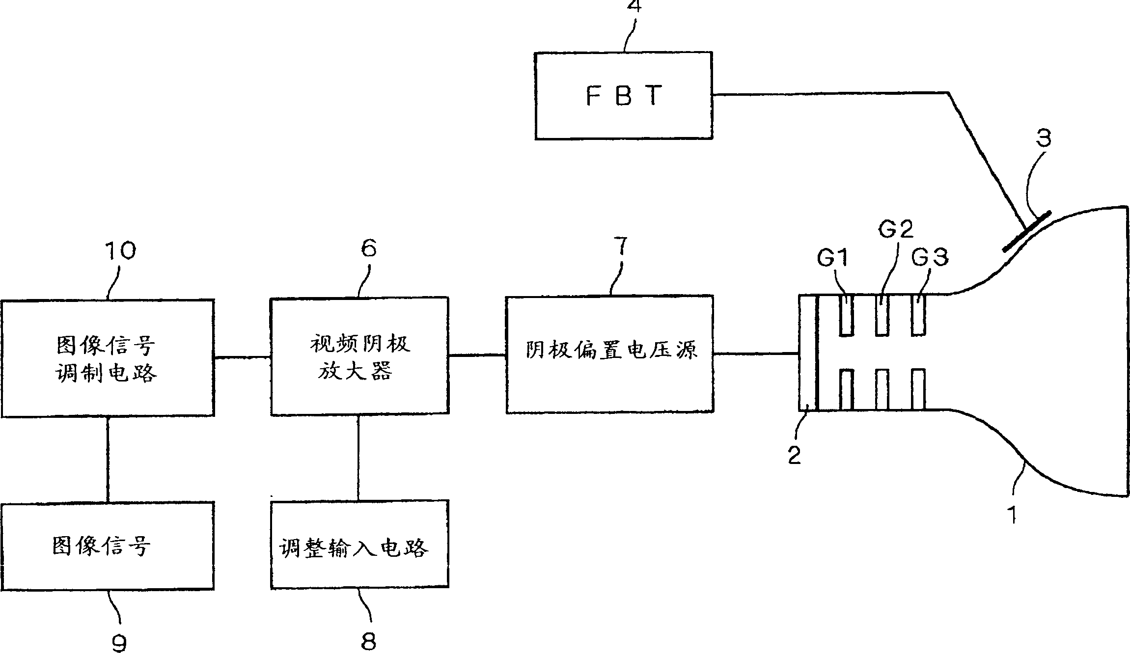
[0027] figure 1 is a schematic configuration diagram of the CRT display device of Example 1. In this figure, for Figure 4 Structural units with the same function are given the same reference numerals, and their detailed descriptions are omitted. 1 is a CRT of MM tube, and CRT1 also includes an electron gun composed of a cathode 2 for emitting electrons, a first electrode G1, a second electrode G2, a third electrode G3, and an anode 3. In this figure, focusing electrodes and the like arranged after the third electrode G3 are also omitted for simplification of description.
[0028] The diameter of the electron through hole in the first electrode G1 and the electrode plate thickness of the electron through hole part, the diameter of the electron through hole in the second electrode G2 and the electrode plate thickness of the electron through hole part, the first electrode G1 and the second electrode The various parameters of the distance between G2 satisfy the following relat...
Embodiment 2
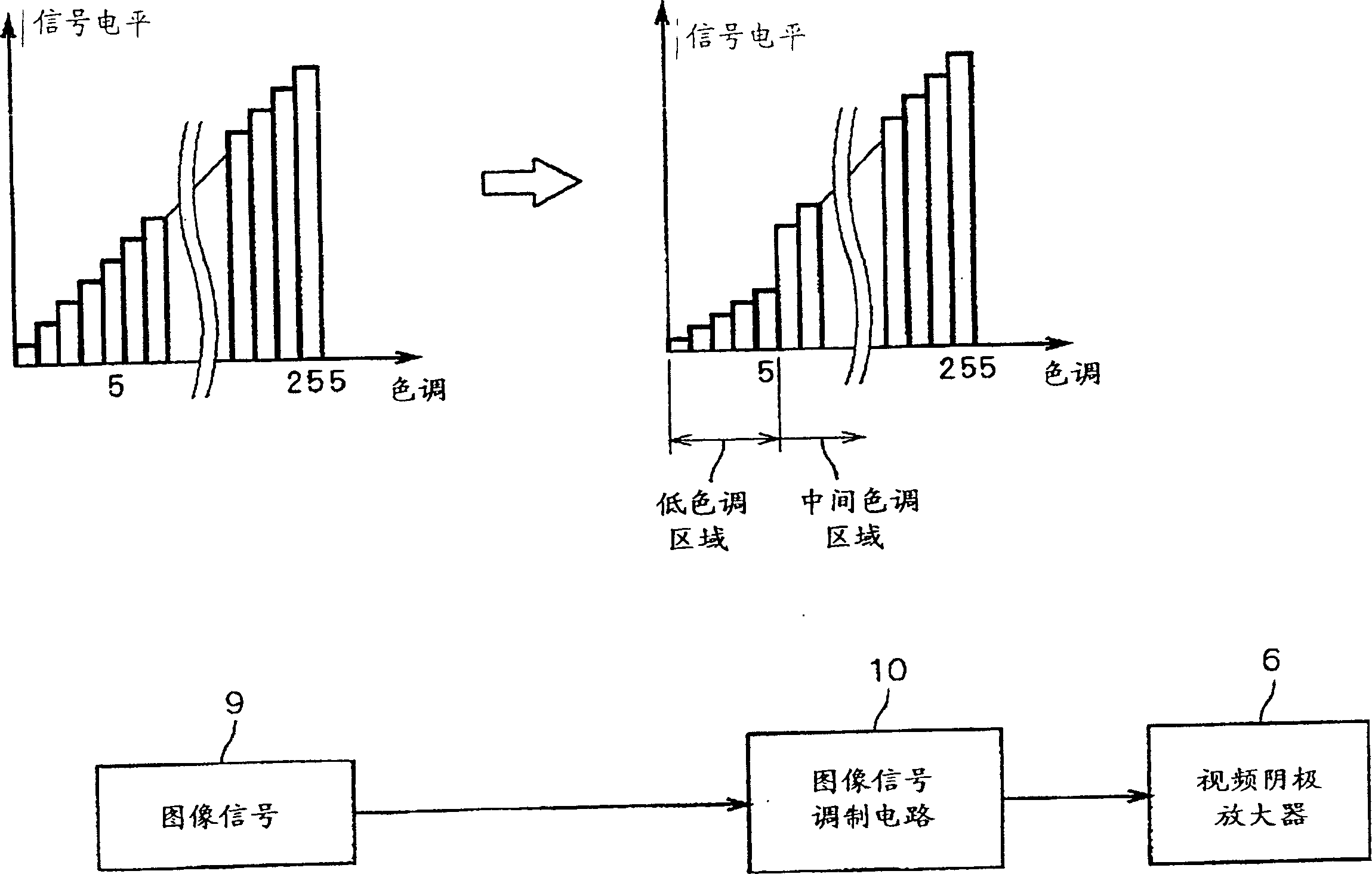
[0061] For example in figure 2 In the second image signal shown, the shift in signal level is large in the low-tone area where the signal level is suppressed compared with the first image signal, and in the boundary between the mid-tone and high-tone areas. When such a second image signal is used, the image will be displayed with a lowered tone due to the tone near the boundary. Since this boundary exists in a relatively low-tone area, there is a problem that the tone of particularly dark graphics (for example, night scenes) is significantly lowered in an image showing a lot of low-tone black.
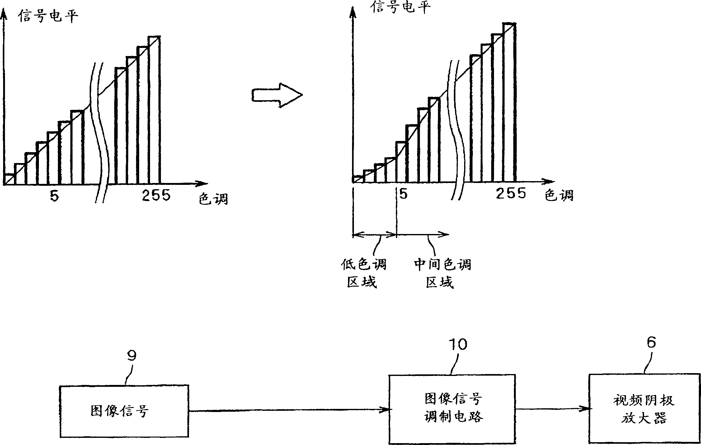
[0062] In the second embodiment, this problem should be solved, and the sudden change of the signal level at the boundary between the signal level of the low tone area and the signal level of the high tone area in the second image signal output from the image signal modulation circuit 10 should be suppressed.
[0063] image 3 It is a diagram illustrating the operation of the image ...
PUM
 Abstract
Description
Claims
Application Information
 - R&D
- Intellectual Property
- Life Sciences
- Materials
- Tech Scout
- Unparalleled Data Quality
- Higher Quality Content
- 60% Fewer Hallucinations
Browse by: Latest US Patents, China's latest patents, Technical Efficacy Thesaurus, Application Domain, Technology Topic, Popular Technical Reports.
© 2025 PatSnap. All rights reserved.Legal|Privacy policy|Modern Slavery Act Transparency Statement|Sitemap|About US| Contact US: help@patsnap.com


