
Oscillator and phaselocked loop using the same

A technology of voltage-controlled oscillators and capacitors, applied in the field of phase-locked loops, can solve the problems of output frequency deviation of voltage-controlled oscillators, difficulty in generating clock signals, etc.

Inactive Publication Date: 2005-01-05
SPANSION LLC
View PDF0 Cites 1 Cited by
  • Summary
  • Abstract
  • Description
  • Claims
  • Application Information

AI Technical Summary

Problems solved by technology

Therefore, the output frequency of the voltage-controlled oscillator will also deviate due to the manufacturing process, so that it is difficult for this voltage-controlled oscillator to generate a clock signal whose frequency is precisely controlled by the input voltage

Method used


Image

  • Oscillator and phaselocked loop using the same
  • Oscillator and phaselocked loop using the same
  • Oscillator and phaselocked loop using the same

Examples


Embodiment Construction

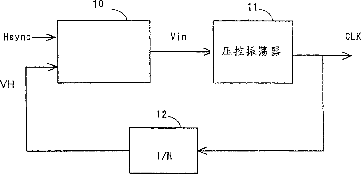
[0045] figure 1 A general phase-locked loop is shown in block diagram form. like figure 1As shown, the phase-locked loop applied to the digital display device, for example, provides a horizontal synchronous signal Hsync at its input terminal, so as to generate a clock signal CLK synchronous with the horizontal synchronous signal Hsync, and its frequency is the frequency of the horizontal synchronous signal Hsync N times. This phase-locked loop comprises a phase comparator 10, is used for detecting the phase difference or the angle between the horizontal synchronization signal Hsync and a comparison signal VH obtained by carrying out N frequency division to the clock signal CLK; a voltage controlled oscillator (VCO ) 11, which is controlled by the input voltage Vin generated by the phase difference detected by the phase comparator 10; and a frequency divider 12, which is used to divide the frequency of the clock signal CLK by N. The voltage controlled oscillator 11 generates...


PUM


Abstract

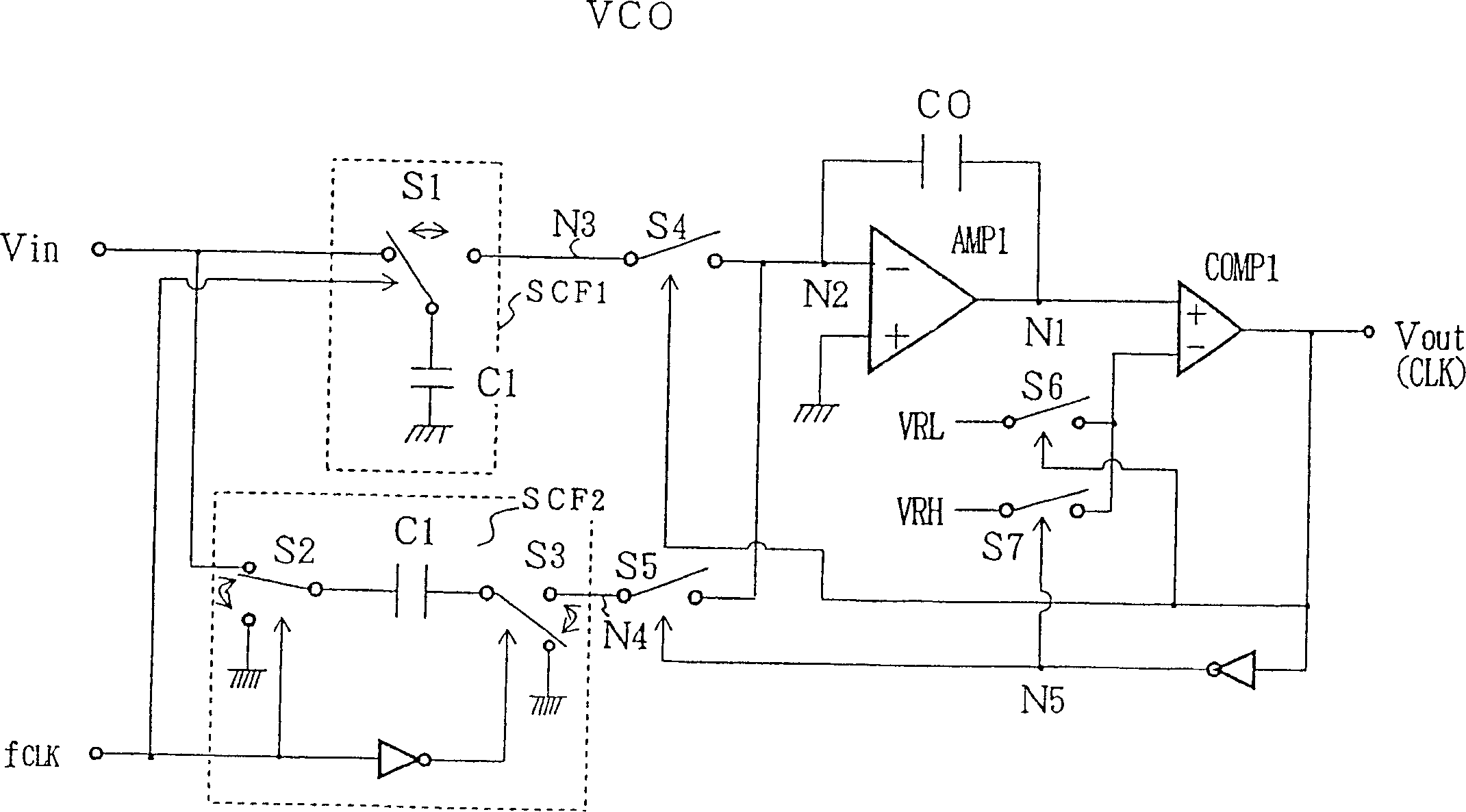
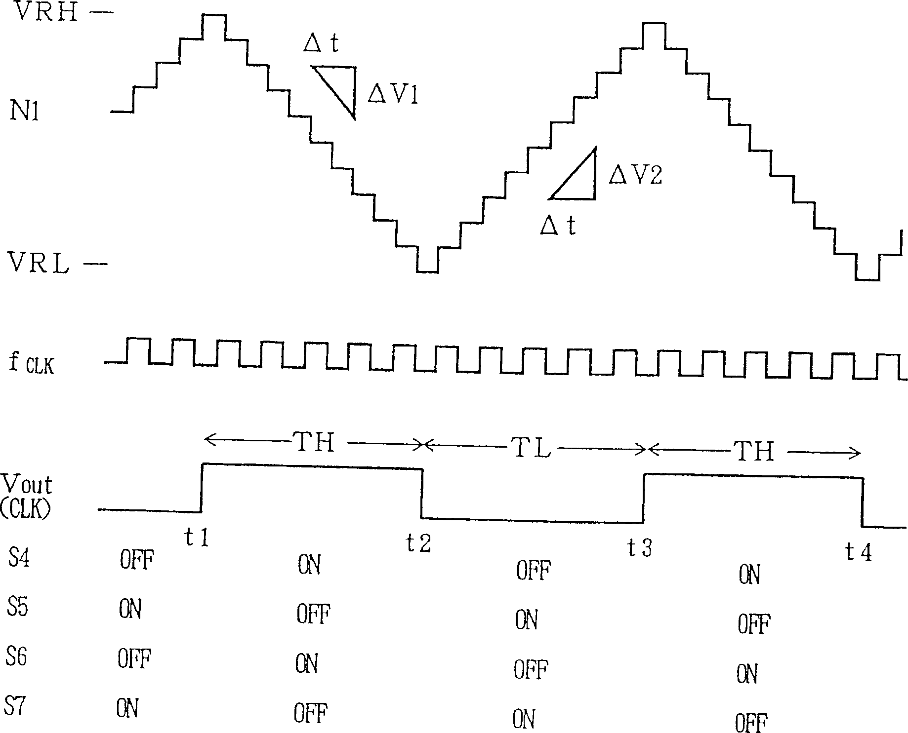
A voltage-controlled oscillator has first and second switched capacitor filters (SCF1, 2), an operational amplifier (AMP1), and a comparator (COM1). The first switched capacitor filter (SCF1) is controlled by a control clock signal to supply a positive current (I1) depending on an input voltage, and the second switched capacitor filter (SCF2) is controlled by the control clock signal to supply a negative current (I2) depending on the input voltage. The operational amplifier (AMP1) has an input terminal (N2) alternately connectable to the first and second switched capacitor filters by a first switch (S4, S5) which can be rendered conductive in synchronism with an output clock signal.

Description

technical field [0001] The present invention relates to a voltage controlled oscillator for generating a clock signal whose frequency is proportional to an applied input voltage, and a phase locked loop (PLL) incorporating such a voltage controlled oscillator. Background technique [0002] Phase-locked loops have been widely used in circuits that generate an output signal that is synchronized with a received signal, in a variety of applications including digital display devices, radio communication devices, and the like. The phase-locked loop usually includes a phase comparator, which is used to compare the phase of the input signal with the phase of the comparison signal generated by dividing the output signal by N; and a voltage-controlled oscillator, which is used to output a signal proportional to the phase difference or the frequency of the voltage depending on the angle. [0003] A traditional voltage-controlled oscillator generates a current that depends on the input...

Claims


Application Information

Patent Timeline
IPC IPC(8): H04N5/12H03H19/00H03K3/0231H03K4/02H03L7/099H03L7/183
CPCH03L7/183H03L7/099H03K3/0231H03H19/004H03K4/023H03L7/00
Inventor 稻波登濑川裕司后藤邦彦
Owner SPANSION LLC
Learn More