Antenna for mobile radio communication

一种移动无线、天线的技术,应用在天线、单独通电的天线阵列、谐振天线等方向,能够解决天线总长度变长、结构复杂、妨碍基地台小型化和低成本化等问题,达到小型结构、特性一致的效果

Inactive Publication Date: 2005-02-23
PANASONIC CORP
View PDF2 Cites 0 Cited by
  • Summary
  • Abstract
  • Description
  • Claims
  • Application Information

AI Technical Summary

Problems solved by technology

In the above-mentioned conventional structure (Fig. 17), in order to realize this point, a multi-stage 1 / 4 wavelength impedance conversion circuit is provided for impedance matching, so the structure becomes complicated, and the total length of the antenna becomes longer at the same time.
In order to ensure the number of channels for mobile wireless communication, this problem has become a major obstacle to the miniaturization and cost reduction of base stations in the process of adding base stations

Method used


Image

  • Antenna for mobile radio communication
  • Antenna for mobile radio communication
  • Antenna for mobile radio communication

Examples


no. 1 Embodiment

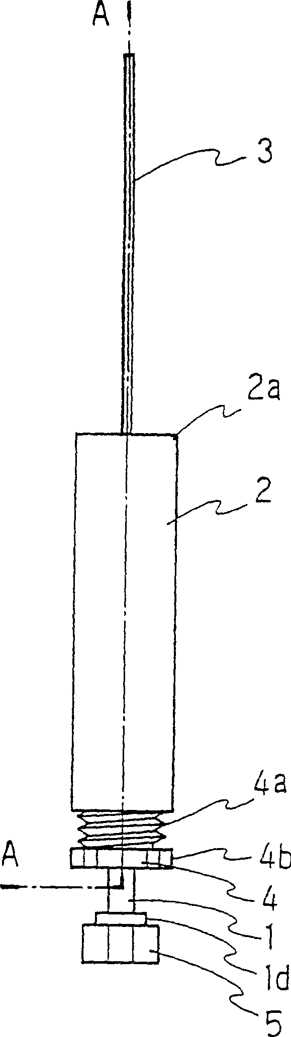
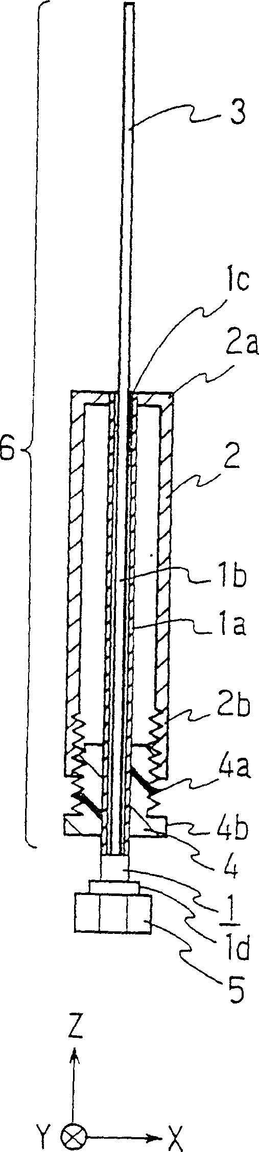
[0050] Fig. 1(a) is a perspective view of a first embodiment of an antenna for mobile radio communication according to the present invention, and Fig. 1(b) is a sectional view taken along line A-A of Fig. 1(a).

[0051] As shown in FIG. 1, the coaxial feeder 1 is composed of an outer conductor 1a and an inner conductor 1b arranged in a concentric circle with a dielectric sandwiched between them. The inner conductor 1b extends upward by about 1 / 4 wavelength from the upper end 1c of the outer conductor 1a. And formed. The antenna element 3 is constituted by the extended inner conductor 1b. On the outside of the coaxial feeder 1 , a cylindrical metal tube 2 made of brass having a wavelength of 1 / 4 is arranged with one end connected to the upper end 1 c of the outer conductor 1 a. At the open end of the metal pipe 2, a female thread 2b is formed on a part of the inner periphery thereof by tapping. An insulating packing 4 made of a fluororesin (for example, polytetrafluoroethylen...

no. 2 Embodiment

[0064] image 3 It is a side view of the second embodiment of the mobile wireless communication antenna of the present invention.

[0065] Such as image 3 As shown, the second dipole antenna 8 is connected to the bottom of the first dipole antenna 7 , and the third dipole antenna 9 is connected to the bottom of the second dipole antenna 8 . This constitutes a straight array antenna.

[0066] exist image 3 Here, since the first dipole antenna 7 has the same structure as that of the above-mentioned first embodiment, its description will be omitted. The second and third dipole antennas 8 and 9 are configured as follows. That is, at a predetermined position of the outer conductor of the coaxial feeder 10, a feed point is formed by providing a circular slit 10x having a width of 3 mm. Outside the outer conductor of the coaxial feeder 10, a pair of 1 / 4 wavelength brass cylindrical metal tubes 11 are arranged on both sides of the annular slit 10x. At this time, the opposite e...

no. 3 Embodiment

[0076] Fig. 6(a) is a cross-sectional view of a third embodiment of the antenna for mobile radio communication according to the present invention, and Fig. 6(b) is a longitudinal sectional view thereof. As shown in FIG. 6 , the coaxial feeder 15 is composed of an outer conductor and an inner conductor concentrically arranged with a dielectric therebetween, and the inner conductor is formed to extend upward by about 1 / 4 wavelength from the upper end 15a of the outer conductor. An internal conductor formed by extending this constitutes the antenna element 16 . On the outside of the coaxial feeder 15, a metal tube 18 made of brass having a wavelength of about 1 / 4 is arranged in a state where one end 17a is connected to the upper end 15a of the outer conductor. The other end 18b of the metal pipe 18 is supported by inserting a gasket 16a made of fluororesin (for example, polytetrafluoroethylene) between the inner wall and the coaxial feeder 15 at the open end 18b of the metal pipe...


PUM


Abstract

A narrow and light mobile radio antenna that requires convenient supporting metal fittings provided in a base station is provided. An inner conductor (1b) of a coaxial feed line (1) extends upward by a length of 1 / 4 wavelength from the upper end (1c) of an outer conductor (1a). This extended inner conductor (1b) forms an antenna element (3). Outside the coaxial feed line (1), a 1 / 4-wavelength sleeve-like metal pipe made of brass (2) is located with one end connected to the upper end (1c) of the outer conductor (1a). On a part of the inner surface of the open end of the metal pipe (2), an internal thread (2b) is formed by tapping. In the open end of the metal pipe (2), an insulating spacer (4) having an external thread (4a) formed around its periphery is inserted. In other words, the insulating spacer (4) is located between the inner wall of the metal pipe (2) and the outer conductor (1a) of the coaxial feed line (1). At the lower end (1d) of the coaxial feed line (1), a coaxial connector (5) for connection with an external circuit is provided.

Description

[0001] This application is a divisional application of an invention patent application with an application date of February 20, 1997, an application number of 97102476.6, and an invention title of "antenna for mobile wireless communication". field of invention [0002] The present invention relates to base station antennas mainly used in mobile radio communications. Background technique [0003] As an antenna for a base station in mobile radio communication or the like, a dipole antenna having a structure called a "coaxial dipole antenna" is mainly used. FIG. 15 shows an example of a conventional coaxial dipole antenna (for example, JP-A-8-139521). As shown in FIG. 15 , outside the outer conductor 50 a of the coaxial feeder 50 , a cylindrical metal tube 51 having a wavelength of about 1 / 4 is arranged with one end connected to the upper end of the outer conductor 50 a. In addition, the inner conductor 50b of the coaxial feeder 50 protrudes from the upper end of the outer con...

Claims


Application Information

Patent Timeline
Patent Type & Authority Patents(China)
IPC IPC(8): H01Q1/24H01Q5/15H01Q9/14H01Q9/16H01Q21/10
CPCH01Q9/16H01Q1/246H01Q9/145H01Q5/0072H01Q21/10H01Q5/40
Inventor 汤田直毅小川晃一大友康宏中村弘幸山林正明
Owner PANASONIC CORP
Why Eureka
Try Eureka