Damping blade with piezoelectric material vibration reduction structure

A piezoelectric material and damping structure technology, applied in the direction of blade support components, engine components, machines/engines, etc., can solve the problems of increasing the damping contact surface area, increasing the centrifugal force of the blade, changing the flow part, etc., to increase the blade Effects of dry friction damping, increasing contact dry friction area, and adjusting blade resonant frequency

Active Publication Date: 2015-07-01
XI AN JIAOTONG UNIV
View PDF7 Cites 0 Cited by
  • Summary
  • Abstract
  • Description
  • Claims
  • Application Information

AI Technical Summary

Problems solved by technology

[0005] The above damping structures are all realized based on the dry friction mechanism. However, when the blades are long or subjected to a large excitation force, the damping will be insufficient.
Simply increasing the positive pressure cannot achieve the purpose of increasing the damping. There is an optimal positive pressure in the frictional damping structure. Increasing the area of ​​the damping contact surface will change the flow part on the one hand; on the other hand, it will also increase the additional mass of the blade. , increasing the centrifugal force of the blade, which has a great impact on the safety of the blade

Method used


Image

  • Damping blade with piezoelectric material vibration reduction structure
  • Damping blade with piezoelectric material vibration reduction structure
  • Damping blade with piezoelectric material vibration reduction structure

Examples


Embodiment Construction

[0026] The present invention will be described in further detail below in conjunction with the accompanying drawings.

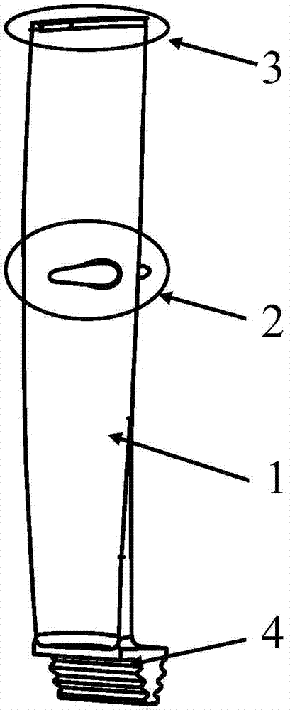
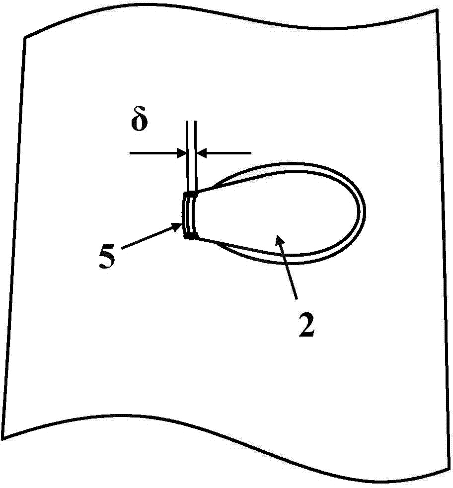
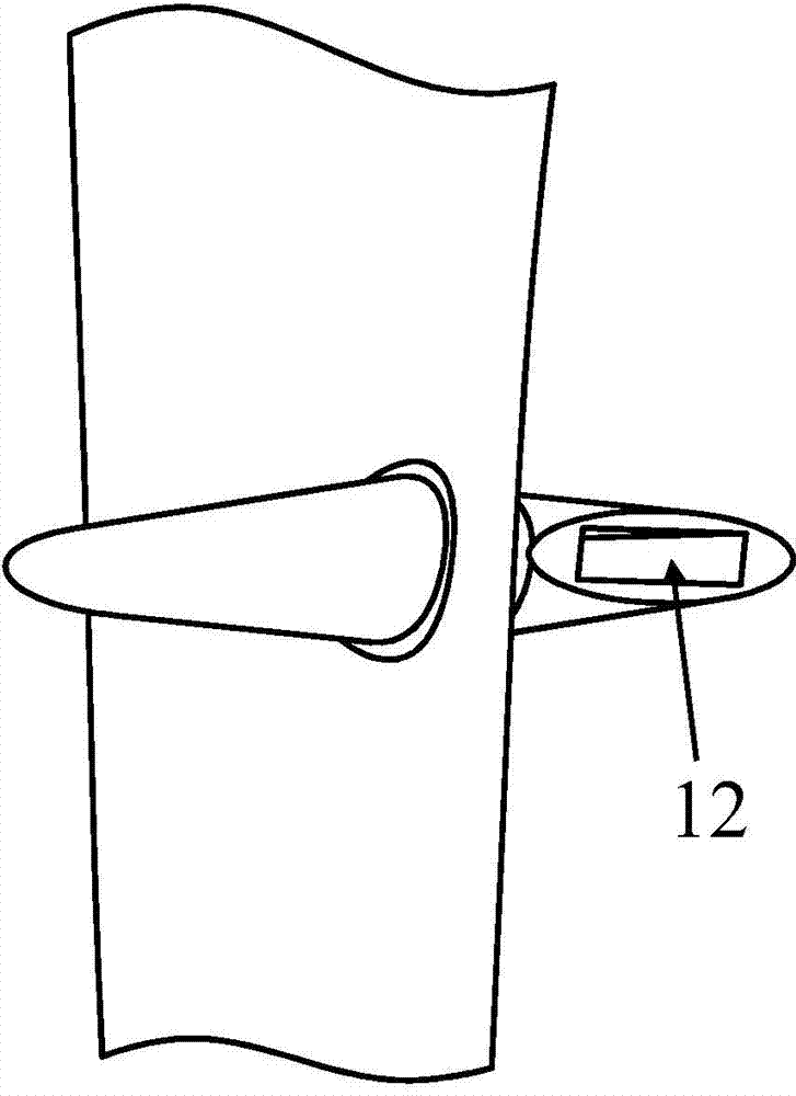
[0027] see Figure 1 to Figure 3 , the damping blade with a piezoelectric material damping structure of the present invention includes: a blade body 1, a blade root 4 and a boss pull 2 ​​arranged on the blade body 1, and the boss pull 2 ​​is provided with a boss pull through Holes 12, a boss pull gold pressure surface contact block 5 is provided on the boss pull gold through hole 12 on the damping blade pressure side side, and a boss pull gold through hole 12 is provided on the damp blade suction side side. The platform pull gold suction surface contact block 6 is provided with an insulating slide block 7 in the boss pull gold through hole 12 between the boss pull gold pressure surface contact block 5 and the boss pull gold suction surface contact block 6. The block 7 has a hollow cavity, and the contact block 5 on the pressure surface of the raised gold pla...


PUM


Abstract

The invention discloses a damping blade with a piezoelectric material vibration reduction structure. The damping blade comprises a blade body, a blade root and a lug boss lashing wire, wherein the lug boss lashing wire is arranged on the blade body and is provided with a lug boss lashing wire through hole, a lug boss lashing wire pressure surface contact block is arranged on the lug boss lashing wire through hole formed in one side of the damping blade pressure surface, a lug boss lashing wire suction force surface contact block is arranged on the lug boss lashing wire through hole formed in one side of the damping blade suction force surface, an insulation slide block is arranged in the lug boss lashing wire through hole arranged between the lug boss lashing wire pressure surface contact block and the lug boss lashing wire suction force surface, the lug boss lashing wire pressure surface contact block is in contact with the insulation slide block through a first piezoelectric material layer, the lug boss lashing wire suction force surface contact block is in contact with the insulation slide block through a second piezoelectric material layer, two electrodes of the first piezoelectric material layer are connected through a first resistor, and two electrodes of the second piezoelectric material layer are connected through a second resistor. The damping blade adopts the piezoelectric vibration reduction damping structure capable of consuming blade vibration energy, so the blade vibration level can be effectively reduced.

Description

【Technical field】 [0001] The invention belongs to the field of impeller machinery, and in particular relates to a damping blade with a piezoelectric material damping structure. 【Background technique】 [0002] As an important power machine in the field of energy conversion and drive, steam turbine plays a pivotal role in national defense security and national economic development. The blade is the most important element of energy conversion in the steam turbine, and its safety is crucial to the safe operation of the steam turbine. [0003] The steam turbine blade is composed of blade root, blade body and shroud structure, and some steam turbine blades have a boss pull gold structure. Studies have shown that vibration is the main cause of damage to steam turbine blades. At present, the main methods to solve this problem are: on the one hand, avoiding the resonance frequency of the blades to reduce the resonance response of the blades; on the other hand, increasing the damping...

Claims


Application Information

Patent Timeline
Patent Type & Authority Patents(China)
IPC IPC(8): F01D5/26
Inventor 谢永慧袁瑞山张荻
Owner XI AN JIAOTONG UNIV
Why Eureka
Try Eureka