Flat battery and electronic device

A technology for plate-shaped batteries and battery cores, applied in battery circuit devices, batteries, small flat batteries/batteries, etc., can solve the problems of complex sealing structure, unstable potential, weak bonding, etc., and achieve improved mechanical strength and improved Adhesive strength, easiness of potential fixation effect

Inactive Publication Date: 2005-04-06
MITSUBISHI ELECTRIC CORP
View PDF0 Cites 0 Cited by
  • Summary
  • Abstract
  • Description
  • Claims
  • Application Information

AI Technical Summary

Problems solved by technology

[0010] Since the previous plate-shaped battery 81 has the above-mentioned structure, the metal foils 5, 9 made of large aluminum sheets in the aluminum laminate film packaging the plate-shaped battery 81 are not connected to the electrodes of the plate-shaped battery 81 to make the potential Floating, thereby making the potential unstable, thus it is impossible to use the internal battery 81a composed of battery cores housed in the aluminum laminated film and the electrical circuit supplied with electric energy by the battery as electrical shielding (electromagnetic shielding, electrostatic shielding). problem of use
[0011] Moreover, regardless of whether polyethylene, polypropylene, polyethylene terephthalate and other polymer resins 4, 6, 8, and 10 have dielectric constants, the outer skin sheets 11, 12 of aluminum laminated films and the like containing these substances There is a problem that it cannot be used as an electronic component such as a capacitor or an antenna
[0012] Since the previous plate-shaped battery 81 must use a sealing resin 7 different from that of the laminated film, the sealing structure is complicated; The problem of sealing
[0013] In addition, since the electrode leads 2, 3 are thin straight plates, the bonding between these electrode leads 2, 3 and the sheath sheets 11, 12 composed of laminated films is relatively weak, and it is easy to pull out the electrode leads 2, 3. Problems with loose direction forward and backward

Method used


Image

  • Flat battery and electronic device
  • Flat battery and electronic device
  • Flat battery and electronic device

Examples


Embodiment approach 1

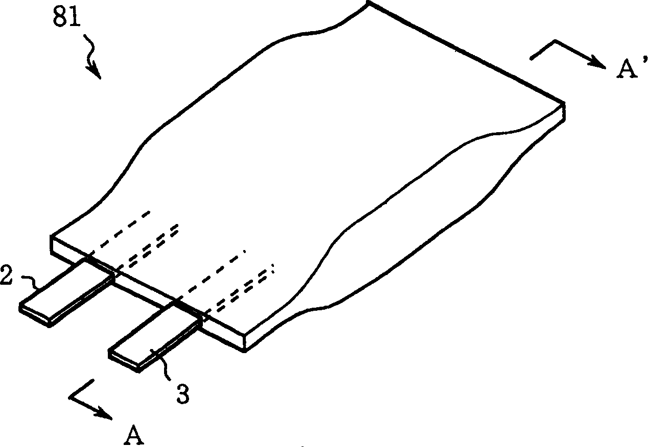
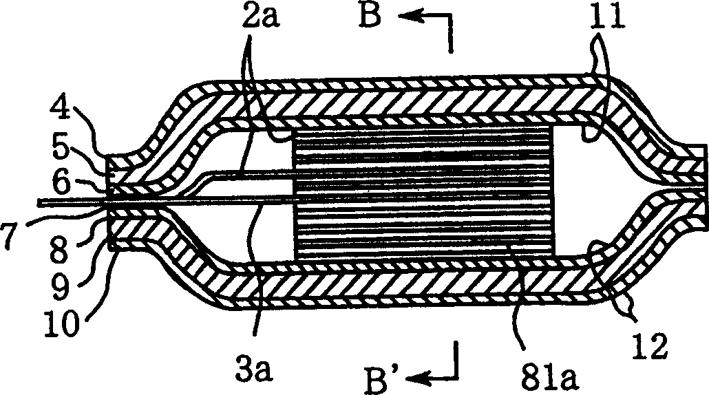
[0097] Figure 4 It is a perspective view showing a plate-shaped battery capable of replenishing or releasing battery energy, such as a nickel-cadmium battery, a nickel-metal hydride battery, and a lithium-ion battery formed in Embodiment 1 of the present invention, Figure 5 is along Figure 4 The cross-sectional view taken on the line C-C', Figure 6 is along Figure 4 Cross-sectional view taken along line D-D'.

[0098] 1 in the figure is a thin plate-shaped battery formed of nickel-cadmium batteries, nickel-hydrogen batteries, lithium-ion batteries, etc., 1a is a battery core, which is used as an internal battery of the plate-shaped battery 1; 21, 20 are positive electrode leads and negative electrode leads, They serve as the input and output terminals of the plate-shaped battery 1; 4, 10 are polymer resins such as polyethylene, polypropylene, polyethylene terephthalate; 5, 9 are metal foils made of metal materials such as aluminum; 11 is a skin sheet that is laminated w...

Embodiment approach 2

[0112] Figure 9 It is a cross-sectional view showing a plate-shaped battery formed in Embodiment 2, which corresponds to the case of the lamination structure shown in the outer skin sheets 11 and 12 described in Modification 2. In the figure, 101 is a connecting portion formed by the positive electrode lead 21 on the extraction hole 19 and a conductor such as the metal foil 5 in the laminated film. Naturally, the negative electrode 20 side also adopts the same structure.

[0113] Below, refer to Figure 9 On the lead wire 21, until the surface of the lead wire is exposed, the outer skin sheet 11 constituting the casing on the box-type electrode is opened to form a take-out hole 19, and the connecting portion 101 is formed here, and is welded, contacted, and the like. The lead wires 21 are electrically connected to the metal foil 5 in the skin sheet 11 forming the laminated film. Therefore, the electric energy input or output of battery, can not be taken out from the box-ty...

Embodiment approach 3

[0117] Figure 10 is a perspective view showing a plate-shaped battery formed in Embodiment 3 of the present invention, Figure 11 is along Figure 10 The cross-sectional view taken along the E-E' line. Among the figure, 16 is on the sheath sheet 11,12 that is electrically connected with positive electrode 21, leads such as aluminum from metal foil 5,9; 23 is the metal foil in laminated film, is to extend from metal foil 5,9 to the side of the housing.

[0118] If the plate-shaped battery 1 formed in Embodiment 3 is used, as Figure 10 As shown, when the metal foils 5, 9 in the laminated film are connected with the positive electrode lead 21 drawn out from the battery core 1a by means of the lead wire 16, it is outside the case, not inside the battery case, and the lead out of the case is drawn out. The L-shaped metal foil 16 is electrically connected to the positive electrode lead 21 . This connecting portion is a position where the position of the metal foil 16 such as ...


PUM


Abstract

A plate-shaped battery comprises: a battery core which has a laminated structure of a sheet-shaped positive electrode and a sheet-shaped negative electrode laminated through a separator, and which has a positive and a negative terminal which are connected electrically to both the electrodes, respectively; and a laminated film which laminates a polymer resin and a metallic foil and which seals both the terminals, and covers the battery core, wherein the metallic foil is connected electrically with a positive or negative pole of the electrodes.

Description

technical field [0001] The present invention relates to a plate-shaped battery and an electronic device, and is particularly concerned with the utilization of a packaging laminated film for a plate-shaped battery and a method for sealing electrode leads of the battery. Background technique [0002] figure 1 It is a perspective view showing the appearance of existing thin plate-shaped batteries capable of replenishing or releasing battery energy, such as nickel-cadmium batteries, nickel-metal hydride batteries, and lithium-ion batteries. figure 2 is along figure 1 A cross-sectional view obtained from the A-A line of the plate battery, image 3 It is a schematic cross-sectional view showing a battery core. [0003] In the figure, 81 is a thin plate-shaped battery made of nickel-cadmium batteries, nickel-hydrogen batteries, lithium-ion batteries, etc., and 2 and 3 are respectively positive electrode leads and negative electrode leads, which constitute the input and output o...

Claims


Application Information

Patent Timeline
Patent Type & Authority Patents(China)
IPC IPC(8): H01M6/50H01M10/04H01M10/42H01M50/105H01M50/119H01M50/121H01M50/124H01M50/178H01M50/55H01M50/553H04M1/02
CPCH01M10/4257H04M1/0262H01M2/20H01M2/06H01M2/0207H01M2200/106H01M2/0275H01M2/1066Y02E60/12H01M10/0436H01M2/30Y02E60/10Y02P70/50H01M50/105H01M50/121H01M50/124H01M50/178H01M50/55H01M50/553H01M50/119
Inventor 花房洁石田博一
Owner MITSUBISHI ELECTRIC CORP
Why Eureka
Try Eureka