Apparatus for vascular embolization

A technology of embolization and tube segments, applied in the field of devices for forming thrombus to occlude blood vessels

Inactive Publication Date: 2005-05-11
MICROVENTION INC
View PDF9 Cites 0 Cited by
  • Summary
  • Abstract
  • Description
  • Claims
  • Application Information

AI Technical Summary

Problems solved by technology

However, as with the conventional microcoil technique, success with the GDC technique has been largely limited to small aneurysms with narrow necks

Method used


Image

  • Apparatus for vascular embolization
  • Apparatus for vascular embolization
  • Apparatus for vascular embolization

Examples


Embodiment Construction

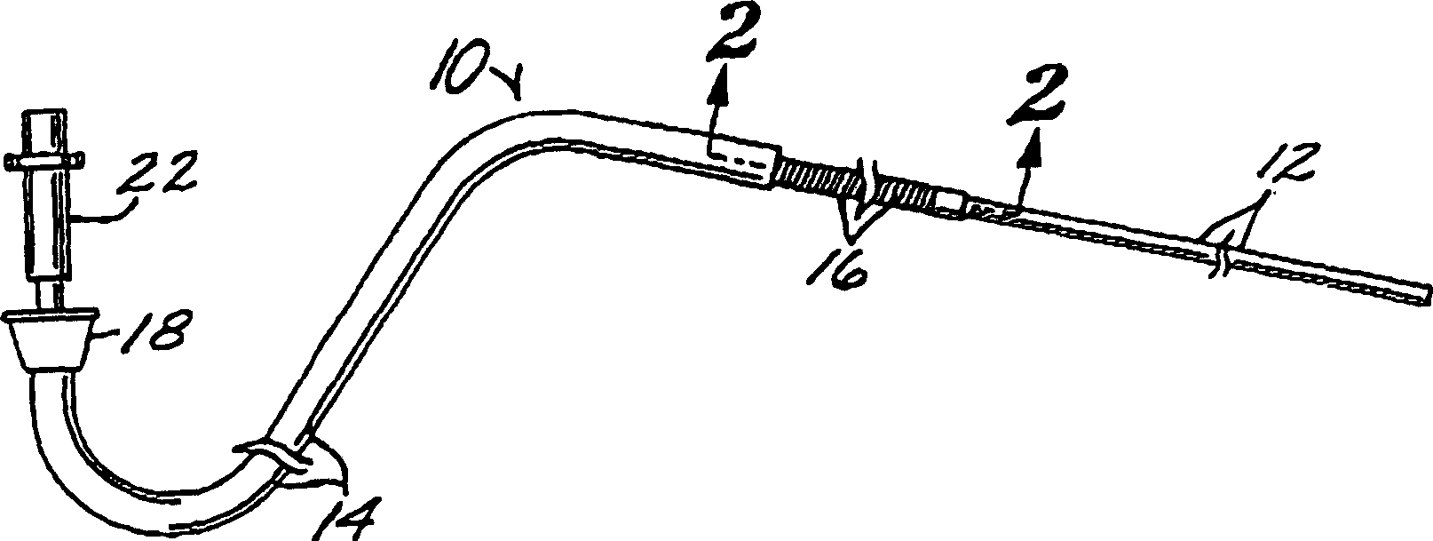
[0033] figure 1 and 2 A preferred embodiment of a device 10 for deploying an embolization device 12 according to the invention is represented. The device 10 comprises a microcatheter 14 having an axial cavity 15 and a delivery tube 16 insertable through the axial cavity 15 of the microcatheter 14 . Microcatheter 14 is of conventional design and there are many microcatheters suitable for use with device 10 available in the market. The proximal end of microcatheter 14 is provided with a funnel 18 for connection to a source (not shown) of a fluid (eg, saline solution) whose flow facilitates the passage of tubing 16 through microcatheter 14, as will be described below. The microcatheter 14, or at least its distal end, is preferably fabricated from a radiopaque material, such as a biocompatible metal. Alternatively, it can be fabricated from a suitable plastic with a radiopaque stopper (not shown) near its distal end, as is known in the art.

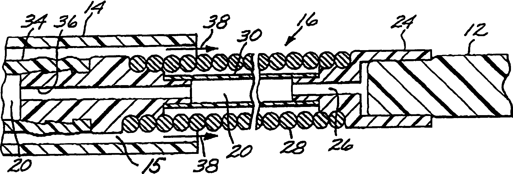
[0034] Deployment tube 16 is a lon...


PUM


Abstract

A vascular embolization device deployable via a microcatheter, comprising a flexible elongated deployment tube sized for insertion through the lumen of the microcatheter, and a filamentary embolization device, Releasably attached to the distal end of the deployment tube, the embolization device can be controllably converted from a soft, compliant state to a rigid or semi-rigid state. The embolization device may comprise a polymeric material that is transformed by contact with blood or a liquid colder than blood, or it may comprise a metallic material that is transformed by electrical erosion. The plug-forming device may be a continuous filament of compression-molded polymer; an elongated microcoil filled with polymeric material; an elongated multi-segment chain including interconnected portions of the polymer; Or a chain of elongated metal segments fused by electrical erosion. The device is used to occlude the aneurysm by arranging the microcatheter so that its distal end is adjacent to the aneurysm; the embolization device is placed into the aneurysm through the microcatheter to form a network mass in the aneurysm; and the device is removed from the soft , the flexible state can be controllably transformed into a rigid or semi-rigid state. The embolization device is preferably deployed by being releasably attached to a flexible elongated deployment tube that passes through the microcatheter and, after appropriate placement of the embolization device , to detach the embolization device from the tube.

Description

technical field [0001] The present invention generally relates to devices and methods for vascular occlusion. More particularly, it relates to devices and methods for occluding a blood vessel by forming a thrombus at a target site in the blood vessel, such as an aneurysm. Background technique [0002] Thrombosis of blood vessels is designed for several clinical situations. For example, thrombosis has been used to control vascular bleeding, to occlude the blood supply to tumors, and to occlude vascular aneurysms, especially within coronary arteries. In recent years, the use of vascular embolization for the treatment of aneurysms has attracted great attention. Several different treatment modalities have been employed in the prior art. For example, US Patent No. 4,819,637 to Dormandy et al. describes a vascular embolization system using a detachable balloon delivered through an intravascular catheter to the site of an aneurysm. A balloon is placed at the tip of the catheter...

Claims


Application Information

Patent Timeline
IPC IPC(8): A61B17/12
CPCA61B17/12022A61B17/12113A61B17/1214A61B17/12163A61B17/12186A61B17/12195A61B2017/1205A61B2017/12063
Inventor 罗伯特·F·罗森布鲁斯布莱恩·J·考克斯乔治·R·小格林
Owner MICROVENTION INC
Why Eureka
Try Eureka