Eureka AIR delivers breakthrough ideas for toughest innovation challenges, trusted by R&D personnel around the world.

In-band common frequency digital cordless telephone

A cordless phone, in-band co-frequency technology, applied in the direction of telephone communication, electrical components, branch office equipment, etc., can solve the problems of low frequency utilization rate, low channel capacity, and low degree of integration of analog cordless phones, and achieve functional Easy to upgrade and expand, high spectrum utilization, and the effect of saving spectrum resources

Inactive Publication Date: 2005-06-29
SOUTH CHINA UNIV OF TECH
View PDF0 Cites 0 Cited by
  • Summary
  • Abstract
  • Description
  • Claims
  • Application Information

AI Technical Summary

Problems solved by technology

There are many deficiencies in analog telephones: first, analog cordless telephones transmit analog signals, the signal processing method is simple, the power consumption is relatively large, and the influence of interference and noise cannot be effectively eliminated, resulting in unsatisfactory call quality in many cases; Second, the frequency utilization rate of analog cordless phones is not high, and the channel capacity is low. The cordless phone standard formulated in my country in 1994 is 20 pairs of frequencies of 45 / 48MHz, and the frequency bandwidth occupied by each channel is 25kHz; The analog cordless phone uses analog modulation transmission, which is easy to be illegally tapped and eavesdropped, and the security cannot be fully guaranteed; fourth, the analog cordless phone mostly uses discrete components to form a circuit, the degree of integration is not high, the volume is large, and the function consumes more
Therefore, it is difficult to realize, the cost is high, and there is a tendency to be replaced by GSM

Method used

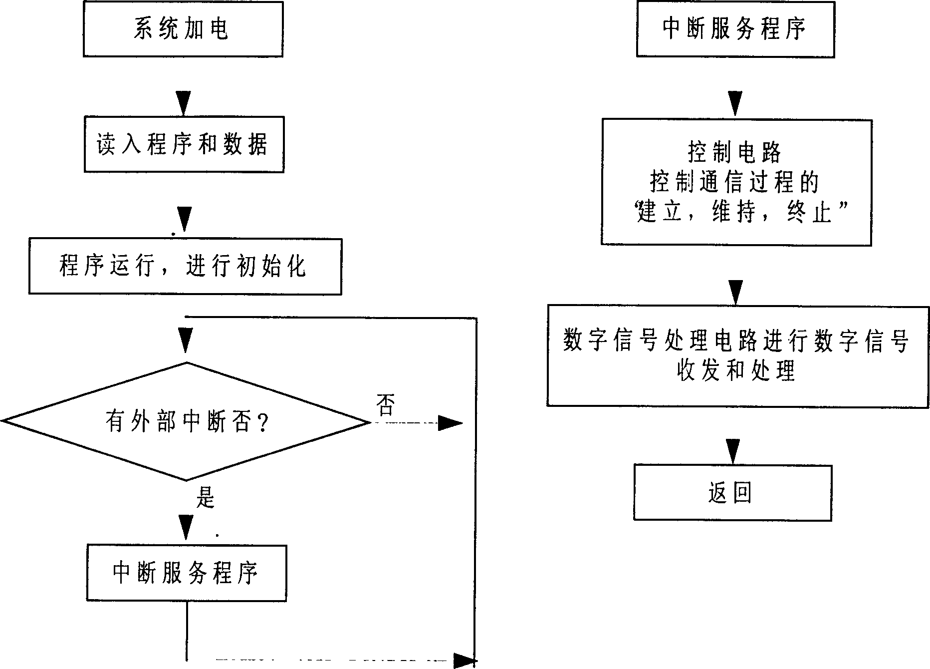
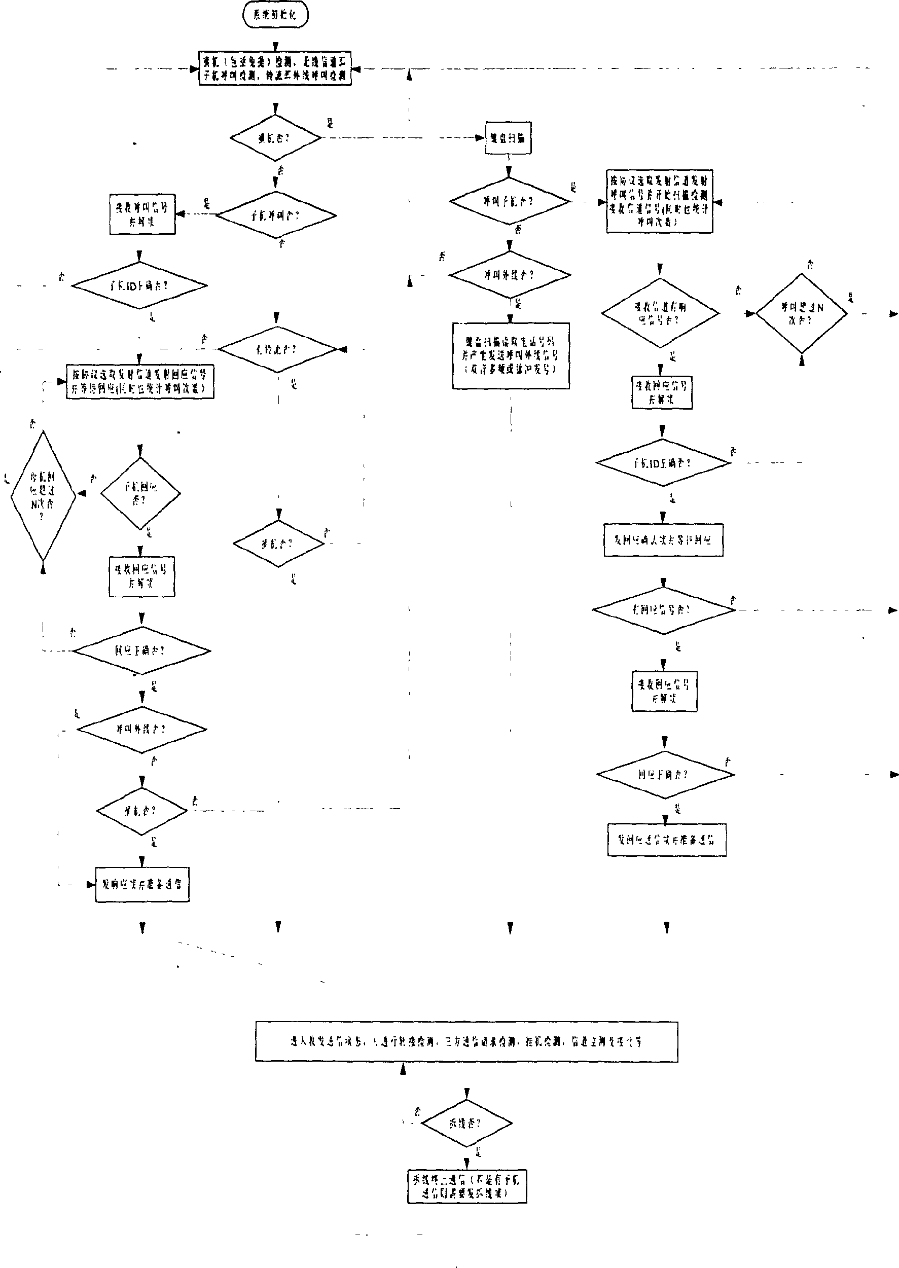

Image

  • In-band common frequency digital cordless telephone
  • In-band common frequency digital cordless telephone
  • In-band common frequency digital cordless telephone

Examples


Embodiment Construction

[0046] The present invention will be described in further detail below in conjunction with the accompanying drawings and embodiments.

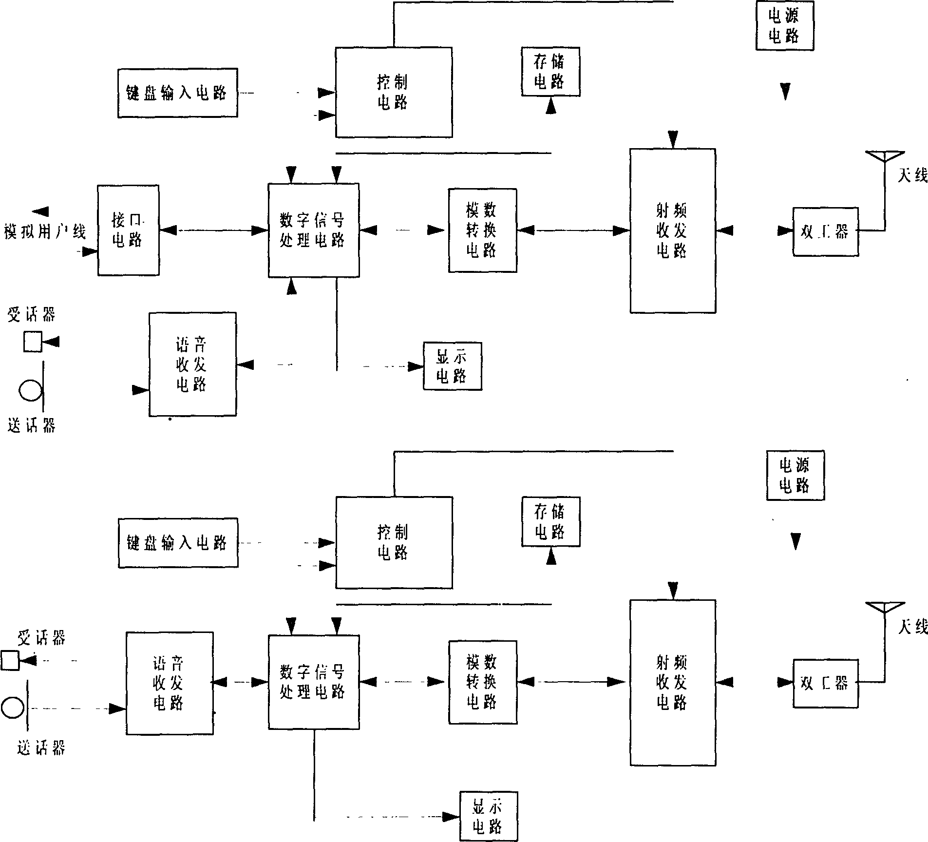
[0047] Such as figure 1 As shown, a kind of in-band co-frequency digital cordless telephone of the present invention is made up of two parts of master machine and slave machine, the system circuit of master machine is composed of control circuit, digital signal processing circuit, radio frequency transceiver circuit, voice transceiver circuit, storage circuit, display Circuit, keyboard input circuit, analog-to-digital conversion circuit, interface circuit and power supply circuit are electrically connected to each other; there is no interface circuit in the system circuit of the sub-machine, and the connection relationship of other circuit parts is the same as that of the main machine. Among them, the control circuit is electrically connected with the digital signal processing circuit, radio frequency transceiver circuit, keyboard input circui...


PUM


Abstract

The present invention is an in-band co-frequency digital cordless telephone, which consists of two parts: a main machine and a slave machine, and its circuit part consists of a control circuit, a digital signal processing circuit, a radio frequency transceiver circuit, a voice transceiver circuit, a storage circuit, a display circuit, and a keyboard input circuit , analog-to-digital conversion circuit, interface circuit and power supply circuit are electrically connected to each other. The present invention adopts the same frequency band as the existing analog cordless telephone in my country, can save precious frequency spectrum resources, greatly reduces requirements on required components and production and testing equipment, and has low cost. The present invention integrates the latest digital signal processing technologies such as speech coding, channel coding, digital modulation and demodulation, and digital channel equalization, and adopts a single-chip integrated circuit chip to realize the advantages of good call quality, high spectrum utilization rate, strong anti-interference, It has the advantages of good confidentiality, easy product update and function expansion, and can be compatible with the third-generation mobile communication system.

Description

(1) Technical field [0001] The invention relates to the technical field of communication, signal processing and software radio, in particular to an in-band co-frequency digital cordless telephone. (2) Background technology [0002] At present, my country's cordless phones are still dominated by analog cordless phones. There are many deficiencies in analog telephones: first, analog cordless telephones transmit analog signals, the signal processing method is simple, the power consumption is relatively large, and the influence of interference and noise cannot be effectively eliminated, resulting in unsatisfactory call quality in many cases; Second, the frequency utilization rate of analog cordless phones is not high, and the channel capacity is low. The cordless phone standard formulated in my country in 1994 is 20 pairs of frequencies of 45 / 48MHz, and the frequency bandwidth occupied by each channel is 25kHz; The analog cordless phone uses analog modulation transmission, which ...

Claims


Application Information

Patent Timeline
Patent Type & Authority Patents(China)
IPC IPC(8): H04M1/725
Inventor 韦岗刘学斌陈芳炯
Owner SOUTH CHINA UNIV OF TECH
Why Eureka
Eureka Blog
Learn More