Laminated optical film, manufacture and use thereof

A liquid crystal display, optical film technology, used in optics, nonlinear optics, instruments, etc.

Inactive Publication Date: 2005-09-21
NITTO DENKO CORP +1
View PDF1 Cites 0 Cited by
  • Summary
  • Abstract
  • Description
  • Claims
  • Application Information

AI Technical Summary

Problems solved by technology

Therefore, the problem can easily occ

Method used


Image

  • Laminated optical film, manufacture and use thereof
  • Laminated optical film, manufacture and use thereof
  • Laminated optical film, manufacture and use thereof

Examples


example 1

[0071] A retardation film composed of polycarbonate and exhibiting a retardation value of 140 nm was produced. A 25 μm thick acrylic-based adhesive layer was formed on the opposite surface of the retardation film. The dichroic polarizer was attached to the phase retarder by adhesive such that the absorption axis of the dichroic polarizer was at an angle of 45 degrees to the retarded phase axis of the phase retarder. In this way, a polarizer including a retardation film was manufactured.

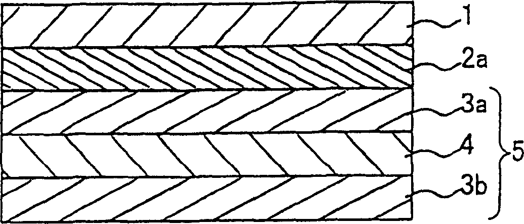
[0072] A 0.1 μm thick PVA alignment film was formed on an 80 μm thick TAC film. After the alignment film was ground, three layers of cholesteric liquid crystal polymers having selective reflection center wavelengths of 400nm, 550nm, and 700nm were formed and sequentially aligned on the alignment film. The thickness of each layer is 3 μm. Then, a λ / 4 sheet of polycarbonate (front-end retardation: 140 nm) was pasted on the cholesteric liquid crystal layer with a 25 µm thick acrylic-based pre...

example 2

[0078] The laminated optical film manufactured in Example 1 and having protrusions was introduced into a liquid crystal module, and a backlight unit reworkability test and an impact test were performed. The introduction of the laminated optical film into the liquid crystal module was carried out as follows. Such as Figure 7 In the configuration shown, the surface of the phase retarder 22 of the laminated optical film 33 is pasted to the rear of the liquid crystal cell 32 . A double-sided adhesive tape 29 (No. 531MC manufactured by Nitto Denko Co., Ltd.) is attached to one protruding portion of the laminated optical film 33 . The protruding portion of the laminated optical film 33 is adhered to the light guide plate 28 of the backlight unit 34 (according to an example of the present invention) by a double-sided adhesive tape 29 .

[0079] Although this example shows the case where No. 531MC manufactured by Nitto Denko was used as the double-sided tape, the same result can be...


PUM


Abstract

A method of producing a laminated optical film constituted by a laminate of a plurality of optical films different in area, the method including the steps of: laminating an optical film (B) having a plurality of rectangular holes parallel to one another, on at least one surface of an optical film (A) to thereby form a laminate; and cutting the laminate into a plurality of chips to thereby obtain laminated optical films.

Description

[0001] This application is based on Japanese Patent Application No. 2001-171964, which is incorporated herein by reference. technical field [0002] The present invention relates to a laminated optical film, which is used in a liquid crystal display device, which has excellent reworkability as well as excellent mechanical properties and excellent dimensional accuracy after the laminated optical film is pasted on a liquid crystal cell, and Methods of manufacturing a laminated optical film and a liquid crystal display device using the laminated optical film are provided. Background technique [0003] As the popularity of cellular phones has progressed in recent years, there have been demands for impact resistance of liquid crystal display elements and space-saving properties of liquid crystal display devices. In order to satisfy these two requirements, it is necessary to connect a backlight unit to liquid crystal cells constituti...

Claims


Application Information

Patent Timeline
IPC IPC(8): G02B5/30G02F1/1335G02F1/13363
CPCG02F1/133528G02F1/1335G02F2202/28G02F1/13363G02F2001/133507G02F1/133507
Inventor 高桥直树河原聪杉浦昭次芦田丈行今井多喜雄
Owner NITTO DENKO CORP
Why Eureka
Try Eureka