Hydraulically controlled pressure releaf valve for high-pressure reactors

A high-pressure reactor and pressure reducing valve technology, which is applied in fluid pressure control, electric fluid pressure control, and non-electrical variable control, etc. Fast cooling effect

Inactive Publication Date: 2005-09-28
BASELL POLYOLEFINE GMBH
View PDF0 Cites 0 Cited by
  • Summary
  • Abstract
  • Description
  • Claims
  • Application Information

AI Technical Summary

Problems solved by technology

Because the response of the hydraulic control mechanism is relatively slow, the

Method used


Image

  • Hydraulically controlled pressure releaf valve for high-pressure reactors
  • Hydraulically controlled pressure releaf valve for high-pressure reactors
  • Hydraulically controlled pressure releaf valve for high-pressure reactors

Examples


Embodiment Construction

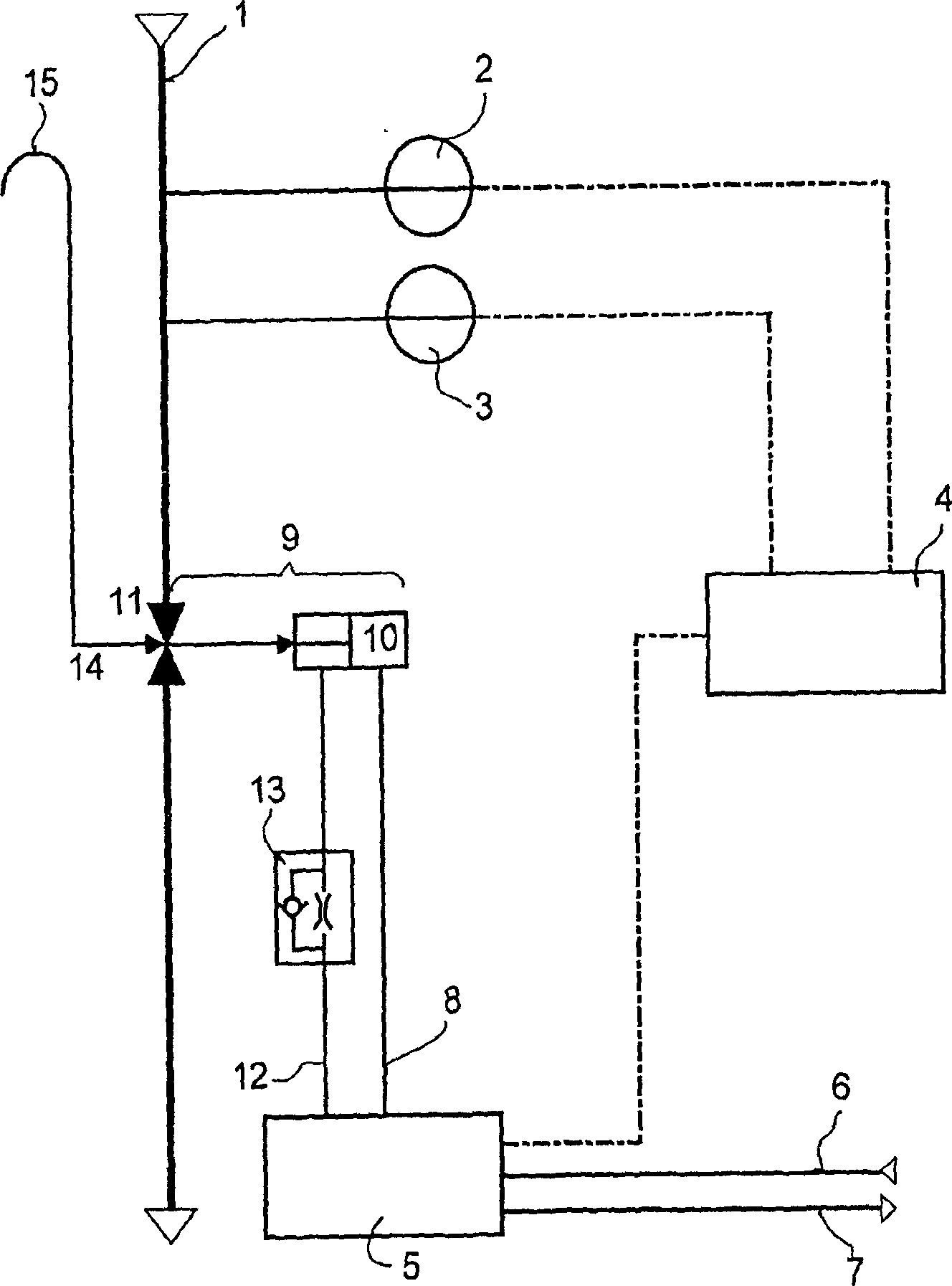
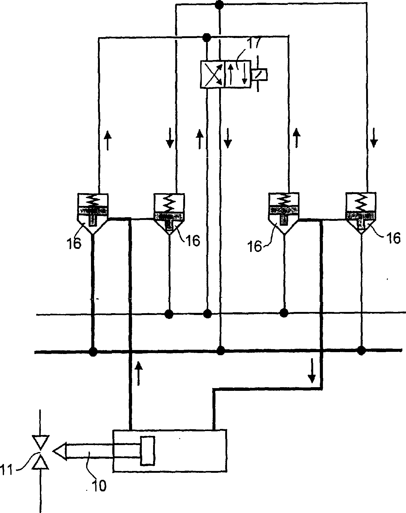
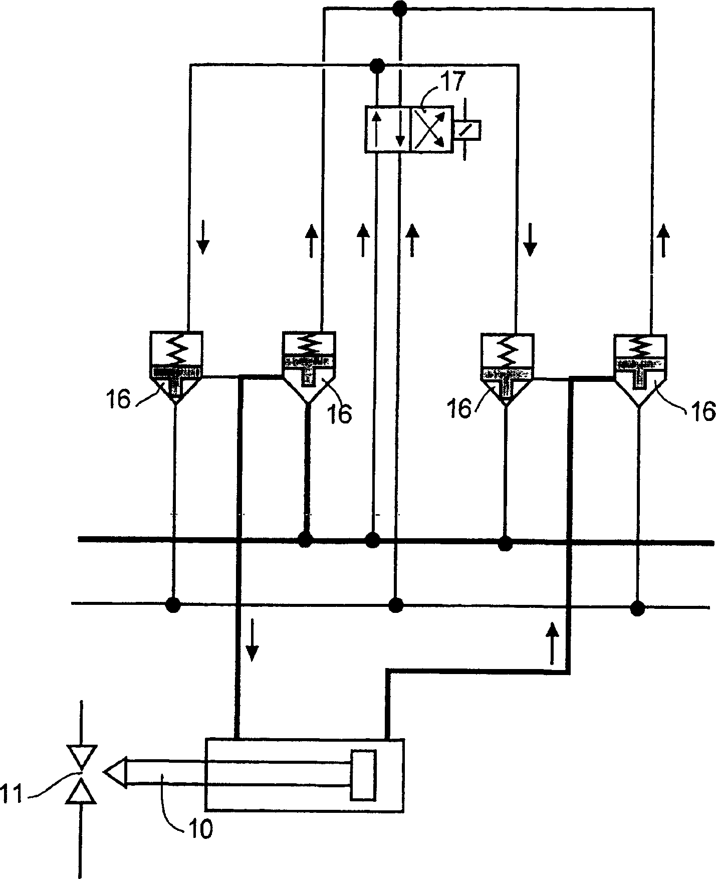
[0026] figure 1 A high-pressure reactor 1 is shown, on which a measuring device 2 for the pressure and a measuring device 3 for the temperature are arranged. An electronic signal is sent from the measuring device 2, 3 to the electronic control system 4 when a predetermined temperature or predetermined pressure is exceeded. The electronic control system sends electronic signals to the hydraulic control unit 5 . A supply pipe 6 and a return pipe 7 of hydraulic fluid are mounted on the hydraulic control unit. Suitable hydraulic fluids are generally commercially available hydraulic oils. A signal to the hydraulic control unit 5 causes one or more valves of the hydraulic control unit 5 to open. The hydraulic fluid is thereby forced to flow through the connecting conduit 8 in the form of a tube in the direction towards the hydraulic system 9 . Accordingly, the movable piston block 10 moves, thereby opening the pressure relief valve 11 . In order to close the pressure relief val...


PUM


Abstract

A high-pressure reactor which has a hydraulically controlled pressure-relief valve. The mechanical design of the corresponding hydraulic system in combination with the control technology used facilitates particularly fast opening of the pressure-relief valve in the case of pressure or temperature jumps in the high-pressure reactor.

Description

technical field [0001] The invention relates to a plant comprising a high pressure reactor with a hydraulically controlled pressure relief valve. Background technique [0002] Compared with low-pressure and medium-pressure polyethylene, high-pressure polyethylene has a higher degree of branching, lower crystal content, lower melting range and lower density. In autoclaving, ethylene is radically polymerized at a temperature between about 150 and 300° C. and at a pressure in the range of about 1500 to 4000 bar. Oxygen or small amounts of peroxide are usually added as free radical initiators. Corresponding reactors can be designed as turbulent flow tank reactors or, preferably, as flow tubes. Suitable tubular reactors generally have a length of from several hundred to several thousand meters and are surrounded on the outside by a heating or cooling jacket. Due to the very high internal pressure in the reactor, the walls of this tubular reactor, made of metal, are usually abo...

Claims


Application Information

Patent Timeline
IPC IPC(8): F15B11/04B01J3/00B01J3/02C08F2/01C08F10/00G05D16/20
CPCG05D16/2013B01J3/04
Inventor 克劳斯·哈默格奥尔格·格鲁斯
Owner BASELL POLYOLEFINE GMBH
Why Eureka
Try Eureka