Platen for flat linear motor

A technology of linear motor and platen, applied in the direction of magnetic circuit shape/style/structure, magnetic circuit static parts, electrical components, etc. Big losses, etc.

Inactive Publication Date: 2005-09-28
SHINANO ELECTRONICS
View PDF1 Cites 0 Cited by
  • Summary
  • Abstract
  • Description
  • Claims
  • Application Information

AI Technical Summary

Problems solved by technology

If the main body of the table made of pure iron is used, since the magnetic flux passing through the main body of the same continuous plate will naturally generate a large range of overcurrent, the AC magnetization characteristics will deteriorate, and the loss of power (iron loss) will be relatively large. Large, so the high speed and h

Method used


Image

  • Platen for flat linear motor
  • Platen for flat linear motor
  • Platen for flat linear motor

Examples


Embodiment 1

[0081] Figure 7 is a perspective view showing the platen described in Example 1, Figure 8 is its front view, Figure 9 is its side view. The platen main body 90 has a backing plate 92 overlapping the inner side of the laminated body 91, that is, the parallel surface of the ribs, and the back side of the backing plate 92 is supported by a plurality of connecting beams 93 having a U-shaped cross section. The connecting beams 93 are provided at each discrete position in the direction of the slab, such as Figure 8 As shown, the connecting beams 93 vibrating right and left with the center of the laminated body 91 as a boundary face each other in opposite directions. The connecting beam 93 has an end portion 94 on the upper folded side, and the end portion 94 on the upper folded side is as Figure 9 As shown, extending in a direction perpendicular to the direction of the rib, along the upper bending side end portion 94, it is injected into the upper bending side end portion 9...

Embodiment 2

[0085] 12 is a perspective view showing the platen according to the second embodiment, Figure 13 is its front view, Figure 14 is its side view. In this example, the same reference numerals are used for the same parts as those in Embodiment 1, and the descriptions thereof are omitted.

[0086] The platen main body 90 of this example does not have the backing plate 92 as in the first embodiment, and directly connects the beams 93 to support the laminated body 91 . This example also has the same stitching member and seam 100A of fluid hardening material as in Example 1, but as Figure 15 As shown, there is no through-hole 92a of the backing plate 92 as in the first embodiment, and an embedded joint portion 102A having a short length of the pin shaft is formed. The joint 100A of the fluid hardening material has a stitching function and a connecting function, but since the backing plate 92 is not provided in this example, the outer frame 81 can be used (refer to Image 6 ) co...

Embodiment 3

[0089] Figure 17 It is a perspective view showing the stapling structure described in Example 3. FIG. In this stitching structure, the opening of the through hole 94b on the upper bending side end portion 94 of the connecting beam is formed into a tapered shape, and the joint 100B of the fluid hardening material is embedded in the upper bending side end portion 94 of the joint portion 102B. A dish-shaped thumbtack head with a flat underneath. The dish-shaped thumbtack head of the embedded joint portion 102B has excellent fracture resistance, and can improve the clamping joint strength with the connecting beam 93 .


PUM


Abstract

A platen used as a stator of a flat linear motor, comprising a platen main body (90) formed of a laminated body (91) of magnetic film (T) and a backing plate (92), wherein a dovetail groove (91a) is formed in the rear surface of the laminated body (91) along the direction perpendicular to the direction of plate streaks, the backing plate (92) comprises a plurality of first through holes (92a) dispersedly arranged in a row in vertical direction through a band-shaped portion facing the dovetail groove (91a), the upper bent end part (94) of a connection beam member (93) comprises a plurality of second through holes (94a) dispersedly arranged in a row in longitudinal direction of the connection beam, and a joint part of fluidizing curing agent formed by filling up and curing the agent in the dovetail groove (91a) and the through holes (94a) and (92a) comprises a buried communicating part (101) fixed to the dovetail groove (91a) and a buried connection part (102) filled into the through holes (94a) and (92a) continuously with the buried communicating part (101) so as to hold the backing plate (92) and the upper bent end part (94).

Description

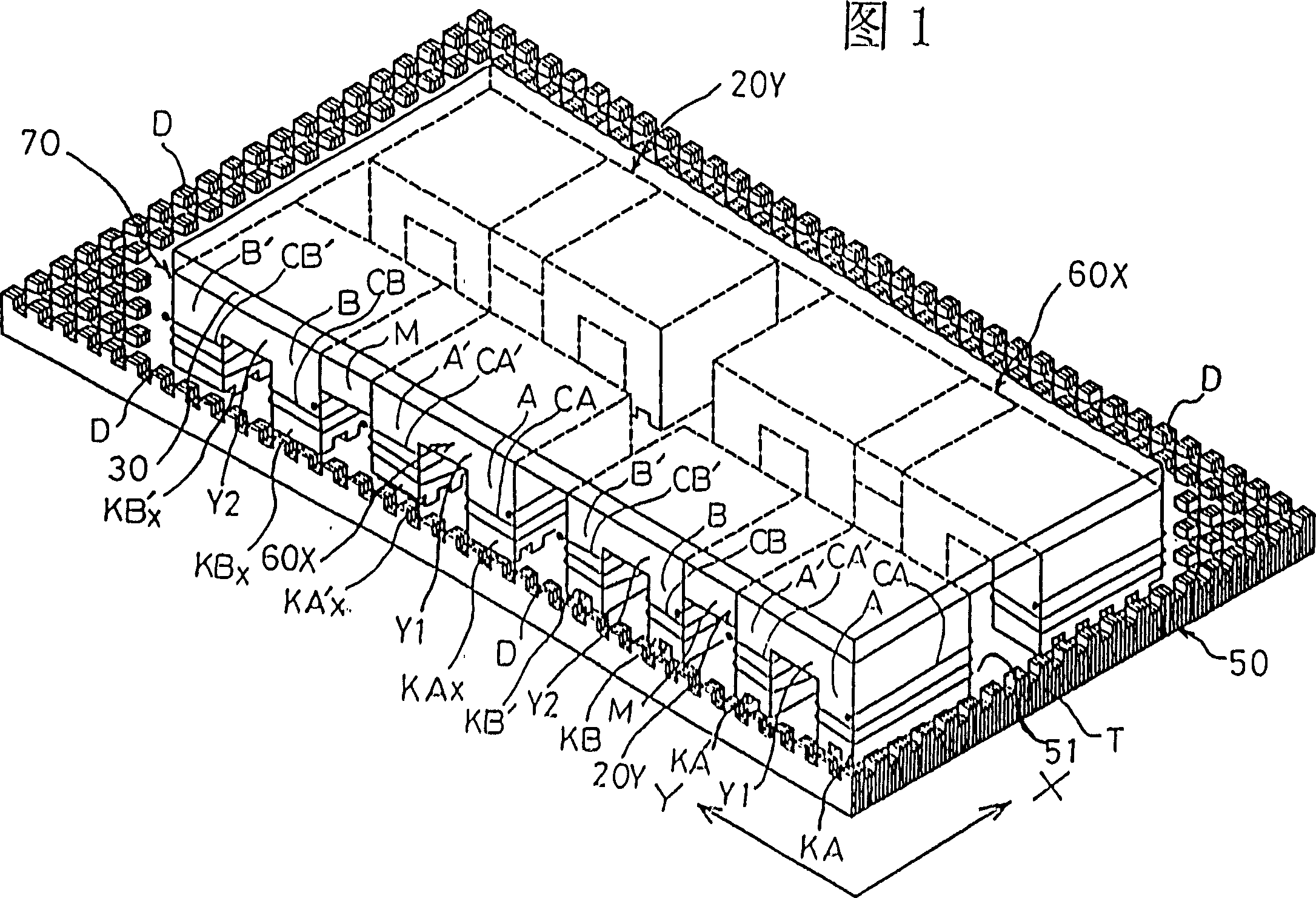
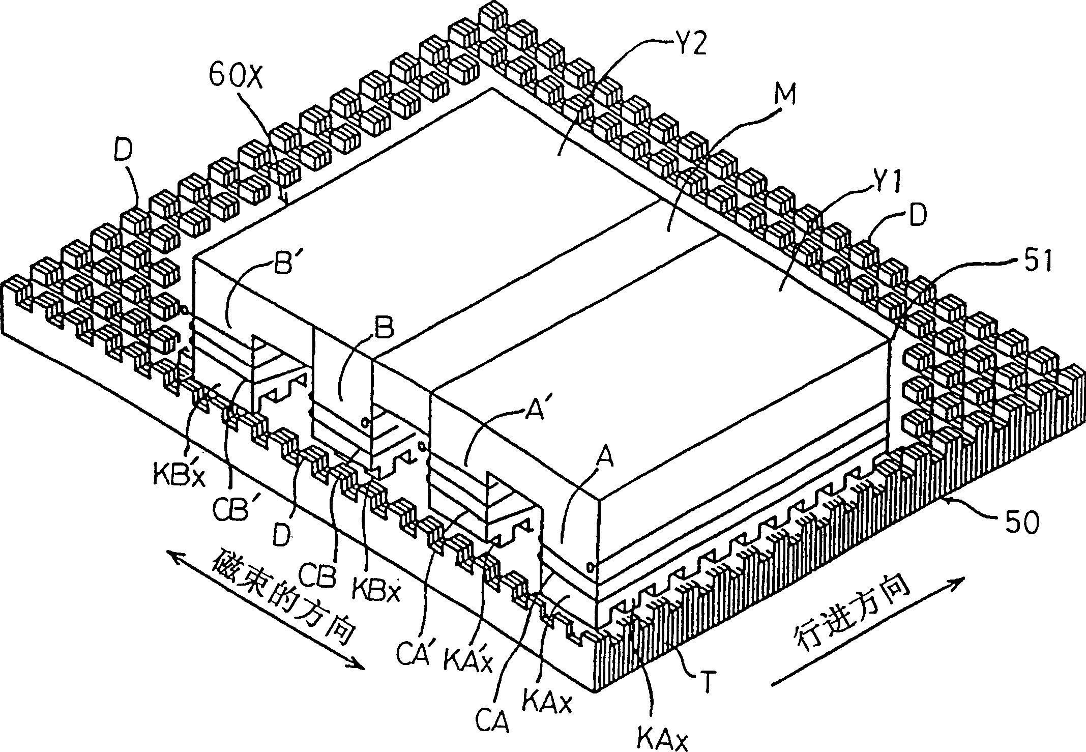
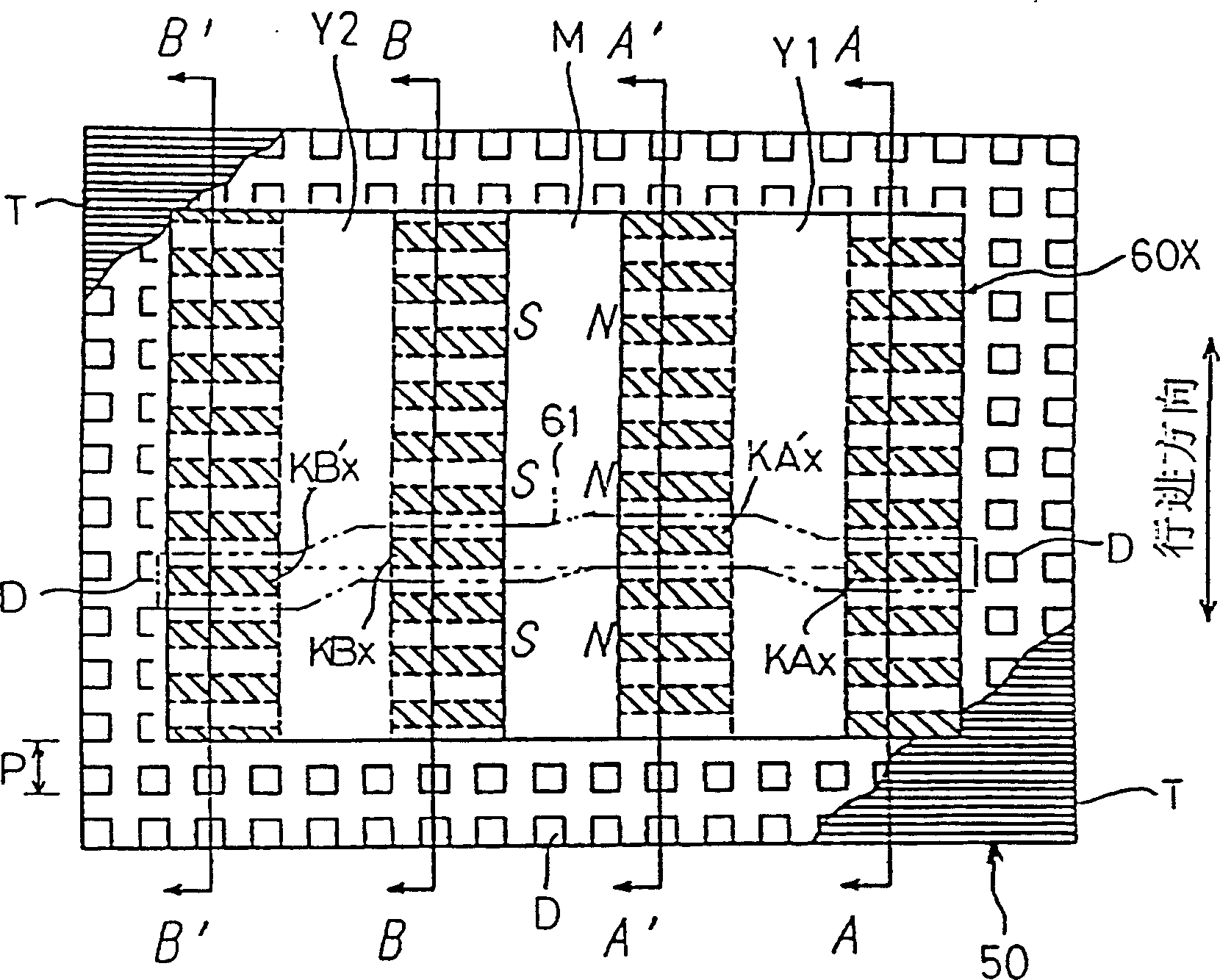
technical field [0001] The present invention relates to a platen as a stator of a planar linear motor, in particular to a platen composed of a plurality of magnetic thin plates. Background technique [0002] First, the principle of the linear motor of the prime tooth (ソ-ヤ) is explained, such as Figure 30 As shown in the figure, the motor consists of a stator and a mover. The stator is on the surface of the magnetic thick plate, and the platen points D are repeatedly scattered with the space cycle of the point pitch P, thereby forming the platen (stator) 10, the mover (walking The body) 20 is composed of the following components: a permanent magnet M for generating a bias magnetic flux, engaged with its magnetic pole face and arranged longitudinally in the traveling direction, with first and second branch magnetic circuit legs A, A'(B, respectively , B') of the first and second yokes (yokes) Y1 (Y2), the first and second yokes in series wound on the first and second branch m...

Claims


Application Information

Patent Timeline
IPC IPC(8): H02K1/18H02K41/03
CPCH02K2201/18H02K41/033H02K1/28H02K41/02
Inventor 伊藤正人田中纪美彦竹内克彦
Owner SHINANO ELECTRONICS
Why Eureka
Try Eureka