Device for electroplating steel band coating

An electroplating device and metal coating technology, applied in the direction of electrodes, electrolysis process, electrolysis components, etc., can solve the problem of high cost and achieve the effect of uniform separation

Inactive Publication Date: 2005-10-05
SMS SCHLOEMANN SIEMAG AG
View PDF0 Cites 0 Cited by
  • Summary
  • Abstract
  • Description
  • Claims
  • Application Information

AI Technical Summary

Problems solved by technology

In order to avoid this adverse effect, the plating process in the prior art will use very high cost pre-leveling equipment

Method used


Image

  • Device for electroplating steel band coating
  • Device for electroplating steel band coating
  • Device for electroplating steel band coating

Examples


Embodiment Construction

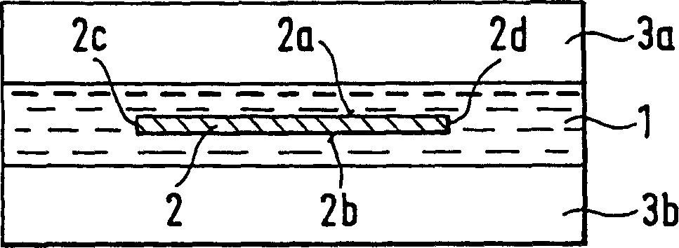
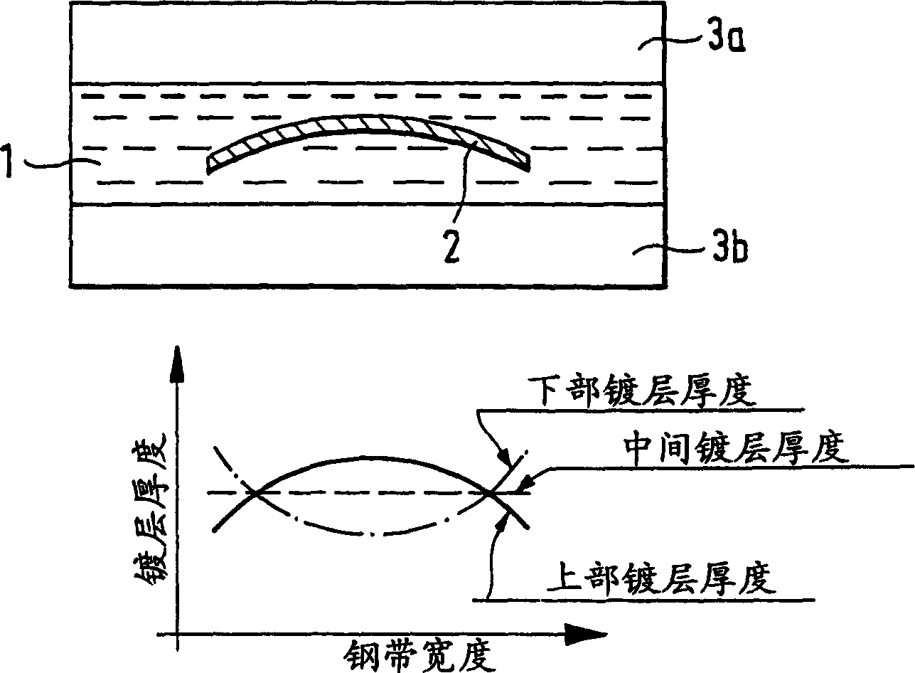
[0035] figure 1 Shown is a steel strip electroplating plant in which a steel strip 2 is immersed in an electrolyte 1 for operation. Parallel to the surfaces 2a, 2b of the steel strip 2, upper and lower anodes 3a, 3b are arranged at a small distance from the surface. The width of the upper and lower anodes 3a, 3b depends on the maximum width of the steel strip to be coated. For example, when the width of the steel strip is 1850mm, the width of the anode can be 2050mm.

[0036] During the metallization process, current flows from the anodes 3a, 3b to the steel strip 2 which works as cathode. Metallic zinc is thus deposited from the electrolyte 1 on the strip surfaces 2a, 2b.

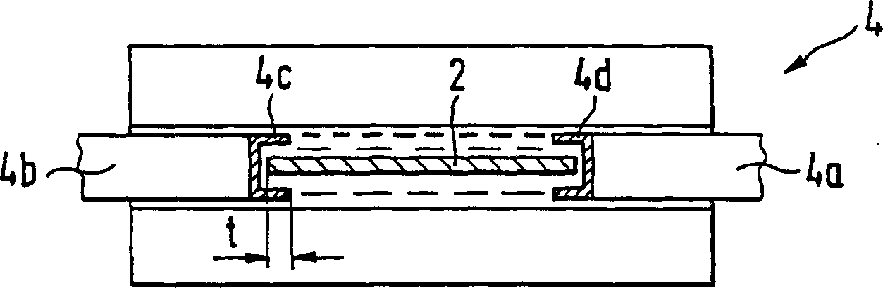
[0037] In order to prevent excessive deposition of metal zinc on the edges 2c, 2d of the steel strip 2, a so-called edge mask 4 is provided in the prior art, such as figure 2 shown. The mask consists of insulating plates 4a, 4b and U-shaped pieces 4c, 4d surrounding the strip edges 2c, 2d.

[0038] ...


PUM

PropertyMeasurementUnit
widthaaaaaaaaaa
thicknessaaaaaaaaaa

Abstract

The invention provide an apparatus for electrogalvanic coating which surely prevents the edge excessly depositing of the separate metal, simultaneously eliminates the difficulties of the apparatus to be used for edge masks. The solution with the above project is that: in the said type apparatus, the respective anodes are divided to several anode stripes in parallel with the moving direction of the band plate and these anode stripes are insulated from each other. A current is passed discretely through each of the respective anode stripes.

Description

technical field [0001] The invention relates to a metallization electroplating device for steel strips running through an acidic electrolyte with metal, said device having at least one insoluble anode arranged parallel to the steel strip, the current flow from The anode flows to the steel strip which acts as the cathode, and metal is deposited from the electrolyte on the surface of the steel strip. Background technique [0002] Cold-rolled strip made of plain carbon steel must be coated with a protective coating to prevent corrosion or at least greatly retard it. The type of protective layer is determined according to its purpose and economically acceptable cost. [0003] What is used in the prior art is a galvanized coating or the like. The corrosion protection of galvanizing is achieved by a metal coating, which is formed electrolytically. [0004] The thickness of the single-side or double-side galvanized steel strip is about 2.5-15 microns, and the device it adopts ha...

Claims


Application Information

Patent Timeline
Patent Type & Authority Patents(China)
IPC IPC(8): C25D17/12C25D7/06C25D19/00C25D21/00
CPCC25D7/0642C25D7/0692
Inventor W·施米安
Owner SMS SCHLOEMANN SIEMAG AG
Why Eureka
Try Eureka