Cascaded pumping system and method for distributed Raman amplification in optical fiber telecommunication system

A technology for distributed and telecommunication systems, applied in the field of optical fiber communication systems and optical fiber Raman amplifiers, and can solve problems such as link performance degradation

Inactive Publication Date: 2005-10-05
MPB TECH
View PDF0 Cites 0 Cited by
  • Summary
  • Abstract
  • Description
  • Claims
  • Application Information

AI Technical Summary

Problems solved by technology

However, this pumping scheme, especially if it is applied to longer spans (eg 125km), requires two relatively expensive, relatively high energy (in the hundreds of mW) sources
This disadvantage is exacerbated in the case of high-capacity WDM systems since the widening of the gain bandwidth requires more such sources
In addition, where the transmitted energy of the signal in the link is at or very close to the limit set by consideration of the reverse nonlinear effects in the fiber, a substantial increase in amplification after the signal is launched can lead to a degradation of link performance due to these nonlinear effects

Method used


Image

  • Cascaded pumping system and method for distributed Raman amplification in optical fiber telecommunication system
  • Cascaded pumping system and method for distributed Raman amplification in optical fiber telecommunication system
  • Cascaded pumping system and method for distributed Raman amplification in optical fiber telecommunication system

Examples


Embodiment Construction

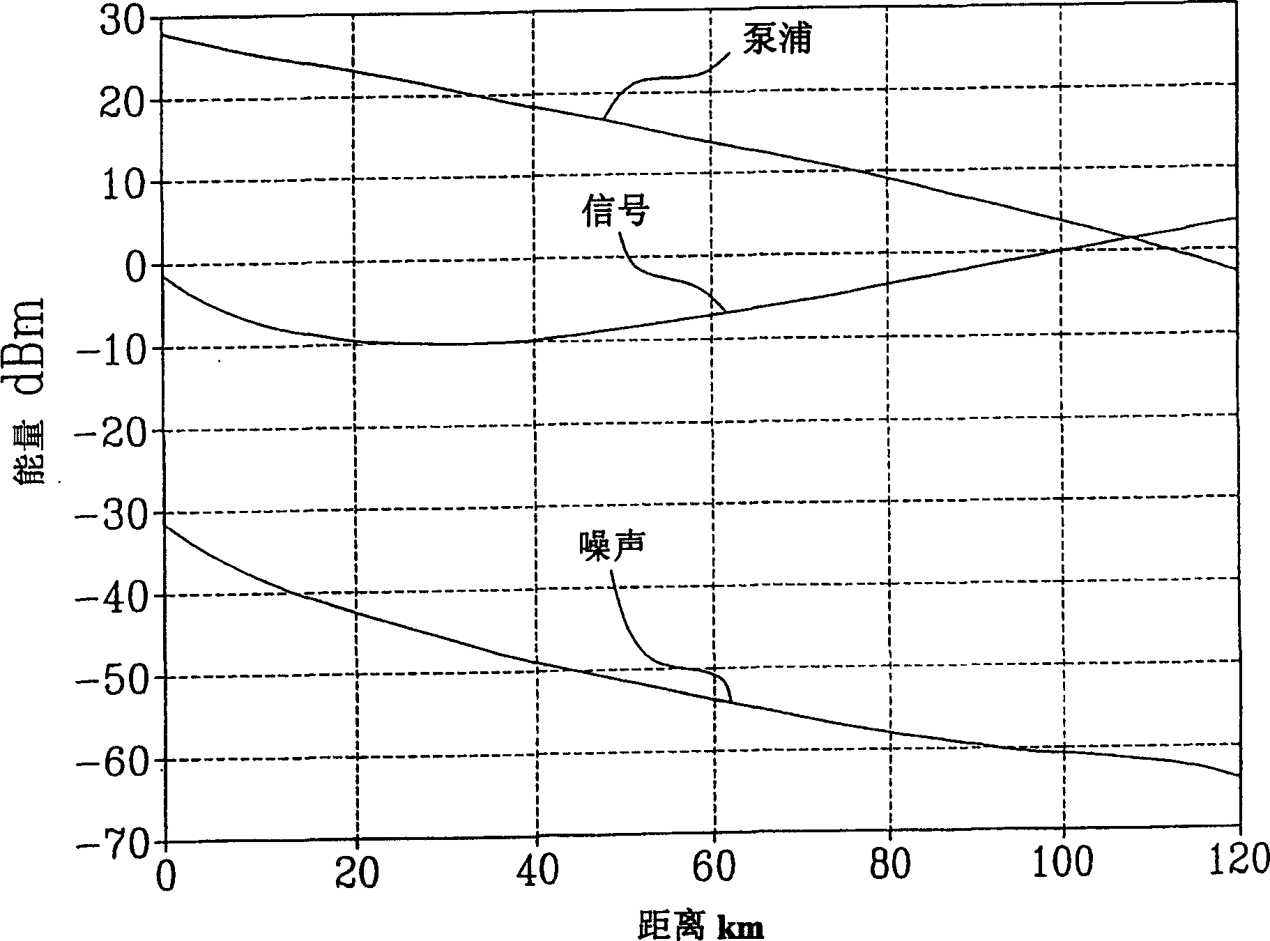
[0028] Two key properties of the distributed Raman amplification process drive the application of distributed Raman amplification in optical fiber telecommunication systems. First, the distributed amplification process provides improved amplified noise performance compared to discrete amplification, since the gain is generated at the rear of the transmission span rather than at the receive or repeater terminals. Second, Raman amplification allows bandwidth amplification because the Raman gain spectrum can be broadened by utilizing several pump wavelengths. The pumping scheme according to the invention can further improve the noise characteristics of distributed amplification, resulting in increased flexibility, effective broadening and dynamic control of the Raman gain spectrum.

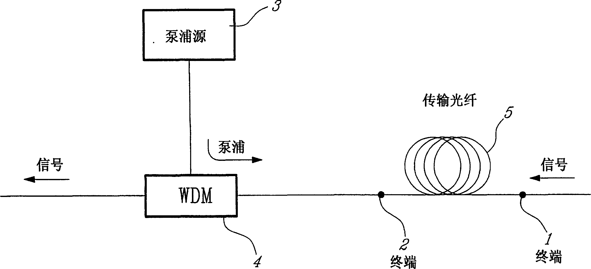
[0029] figure 2 A common optical fiber communication transmission span is shown, which employs distributed Raman amplification and a typical prior art pumping scheme. Terminal 1 may be a sending te...


PUM

PropertyMeasurementUnit
wavelengthaaaaaaaaaa

Abstract

A pumping scheme for distributed Raman amplification (DRA) in optical fiber telecommunication systems is disclosed in which pump energy at the wavelength(s) required for DRA of the transmitted optical signal(s) is developed within the transmission fiber from a primary pump source through a series, n, where n >= 1, of Raman conversions resulting from the launch into the fiber of a primary pump source along with low-power seed sources. Alternatively, seed sources can be replaced by reflecting means to return, into the fiber, backward-travelling amplified spontaneous Raman scattered light resulting from high power in the fiber at a wavelength one Raman shift below the desired seed wavelength. The peak Raman gain thus occurs some distance from the primary pump launch terminal and leads to improved amplifier noise performance. Dynamic control of the magnitude and / or the spectral profile of the distributed Raman gain at, or near, a signal launch terminal can also be provided.

Description

technical field [0001] The present invention relates to a fiber optic Raman amplifier and a fiber optic communication system incorporating such an amplifier, and more particularly to a method for pumping a transmission fiber of a fiber optic communication span to generate in the fiber a signal for amplifying transmission along the fiber span Systems and methods for distributed Raman gain. Background technique [0002] Until recently, the amplification of optical signals in fiber optic communication systems has been initially achieved through the use of discrete optical amplifiers, mainly erbium-doped fiber amplifiers (EDFAs). Due to the explosive growth in the need to increase capacity in fiber optic communication systems, there has been interest in repurposing distributed Raman amplification. See for example, P.B. Hansen et al., IEEE Photonics Technology Letters, Vol. 9(2), p. 262, (February 1997). In this scheme, when the signal is transmitted towards a repeater or recei...

Claims


Application Information

Patent Timeline
Patent Type & Authority Patents(China)
IPC IPC(8): G02F1/35H04B10/17H04B10/29
CPCH04B10/2916
Inventor 塞尔古·帕佩尔内弗拉基米尔·卡尔波夫瓦利西塞·克莱门茨
Owner MPB TECH
Why Eureka
Try Eureka