
Tension member for elevator

A tension member and elevator system technology, applied in the field of tension members, can solve the problems of aramid fiber damage, shortening rope life, and reducing the degree of sheave diameter.

Inactive Publication Date: 2005-10-12
OTIS ELEVATOR CO
View PDF5 Cites 17 Cited by
  • Summary
  • Abstract
  • Description
  • Claims
  • Application Information

AI Technical Summary

Problems solved by technology

The inverse relationship between the sheave diameter D and the rope pressure limits the extent to which sheave diameter reductions can be achieved with ordinary ropes made of aramid fibers
In addition, although aramid fibers have high tensile strength, they are more prone to failure when subjected to transverse loads
Even if the requirement for D / d is reduced, the resulting rope pressure will cause excessive damage to the aramid fiber and reduce the life of the rope

Method used


Image

  • Tension member for elevator
  • Tension member for elevator
  • Tension member for elevator

Examples


Embodiment Construction

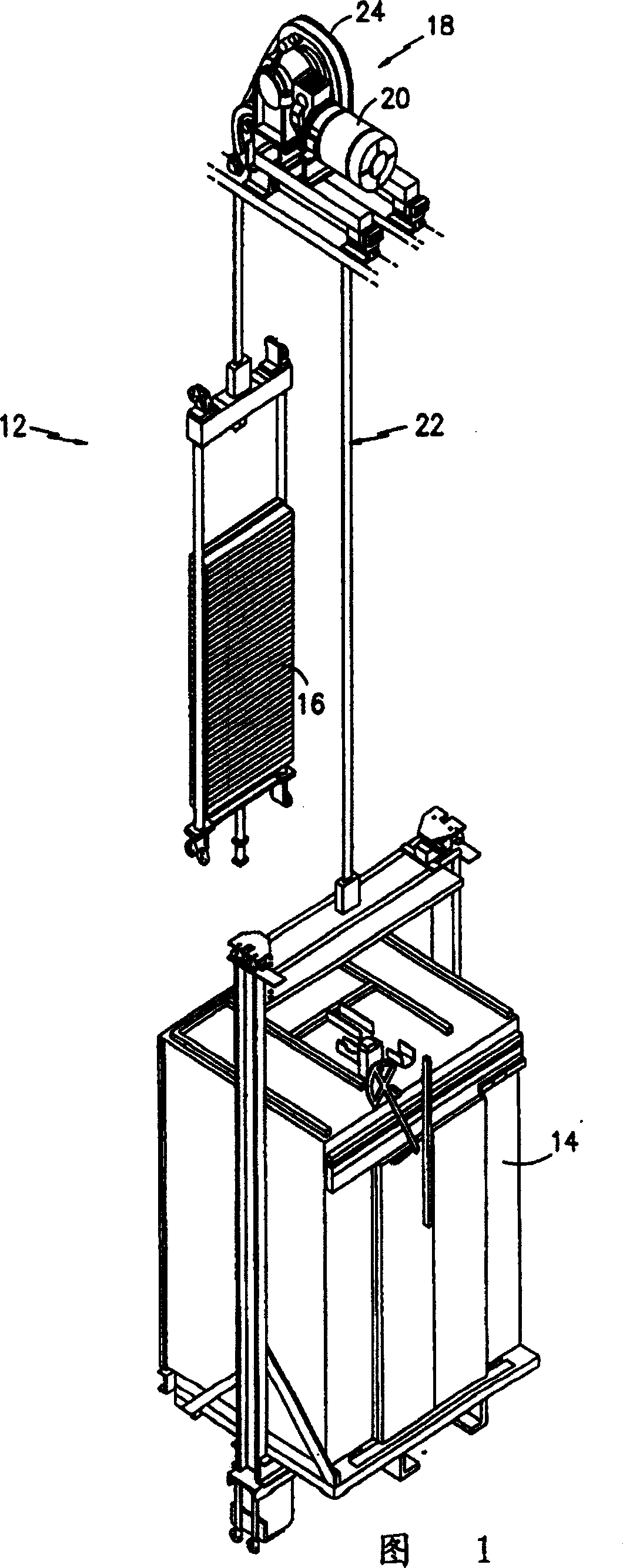
[0030]FIG. 1 shows a traction elevator system 12 . The elevator system 12 includes a car 14 , a counterweight 16 , a traction drive 18 and a main engine 20 . The traction drive 18 includes a tension member 22 interconnecting the car 14 and the counterweight 16 and a traction sheave 24 . The tension member 22 is engaged with the sheave 24, so that the sheave 24 can drive the tension member 22, the car 14 and the balance weight 16 to move when the sheave 24 rotates. The host machine 20 engages with the sheave 24 to drive the sheave 24 to rotate. Although a main engine 20 with a gear box is shown in the figure, it should also be noted that this structure is for illustration purposes only, and the present invention can also adopt a main engine without a gear box.

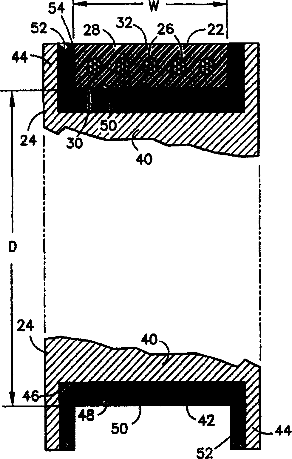
[0031] figure 2 Tension member 22 and sheave 24 are shown in more detail. Tension member 22 is a single unit that gathers a plurality of core wires 26 within a common sheath 28 . Each cord 26 is constructed of para...


PUM

PropertyMeasurementUnit
diameteraaaaaaaaaa
diameteraaaaaaaaaa
diameteraaaaaaaaaa

Abstract

A tension member (22) for an elevator system (12) has an aspect ratio of greater than one, where aspect ratio is defined as the ratio of tension member width w to thickness t (w / t). The increase in aspect ratio results in a reduction in the maximum rope pressure and an increased flexibility as compared to conventional elevator ropes. As a result, smaller sheaves may be used with this type of tension member (22). In a particular embodiment, the tension member includes a plurality of individual load carrying ropes (26), formed from metallic material encased within a common layer of coating. The coating layer (28) separates the individual ropes (26) and defines an engagement surface for engaging a traction sheave (24).

Description

technical field [0001] This invention relates to an elevator system, and more particularly, to tension members for such an elevator system. Background technique [0002] A common traction elevator system includes a car, a counterweight, two or more ropes connecting the car and the counterweight, a traction sheave that drives the ropes, and a host that rotates the traction sheave. The rope is made of parallel or twisted steel wires, and the sheave is made of cast iron. The above-mentioned main engine may have a gear box or may not have a gear box. Engines with gearboxes can use higher-speed motors, which are compact and inexpensive, but require additional maintenance and space. [0003] While common round ropes and cast iron sheaves have proven to be very reliable and inexpensive, their use is limited. One limitation is due to the traction between the rope and the sheave. The above-mentioned traction force can be increased by increasing the wrap angle of the rope, or slot...

Claims


Application Information

Patent Timeline
Patent Type & Authority Patents(China)
IPC IPC(8): D07B1/00B66B7/02B66B7/06B66B7/08B66B7/10B66B9/02B66B11/00B66B13/30B66B15/04B66B17/12D07B1/06D07B1/16D07B1/22
CPCD07B2501/2007D07B1/0673D07B2201/2087B66B7/062B66B7/06B29L2031/707B66B15/04D07B1/22B29C47/003B29C47/027B29C48/12B29C48/156
Inventor P·S·巴兰达A·O·梅洛H·J·奥东内尔
Owner OTIS ELEVATOR CO
Learn More