Pipeline pressure control system of automatic speed-transformation

A technology of automatic transmission and pressure control, applied in transmission control, transmission, fluid transmission, etc., can solve the problems of reduced mileage, difficult to convey pipe pressure, etc.

Inactive Publication Date: 2005-10-19
HYUNDAI MOTOR CO LTD
View PDF0 Cites 0 Cited by
  • Summary
  • Abstract
  • Description
  • Claims
  • Application Information

AI Technical Summary

Problems solved by technology

[0009] However, in the above-mentioned general delivery pipe pressure control system, since the pressure control is accomplished by the pressure from the delivery pipes 212, 214 and 216 to bias the valve plug of the manual valve and the elastic force of the spring 218, it is difficult to effectively and Actively controls delivery line pressure resulting in reduced vehicle mileage

Method used


Image

  • Pipeline pressure control system of automatic speed-transformation
  • Pipeline pressure control system of automatic speed-transformation
  • Pipeline pressure control system of automatic speed-transformation

Examples


Embodiment Construction

[0018] The preferred embodiment of the present invention will be described in detail below in conjunction with the accompanying drawings.

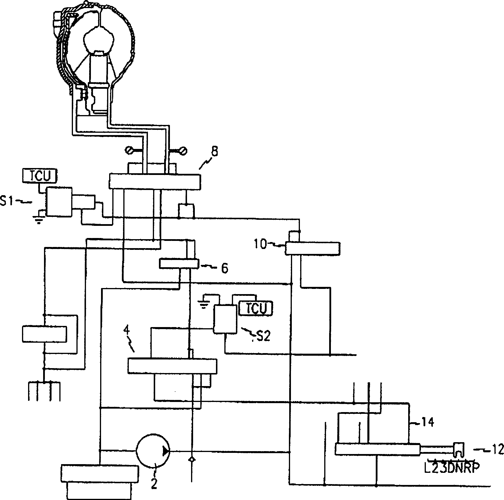
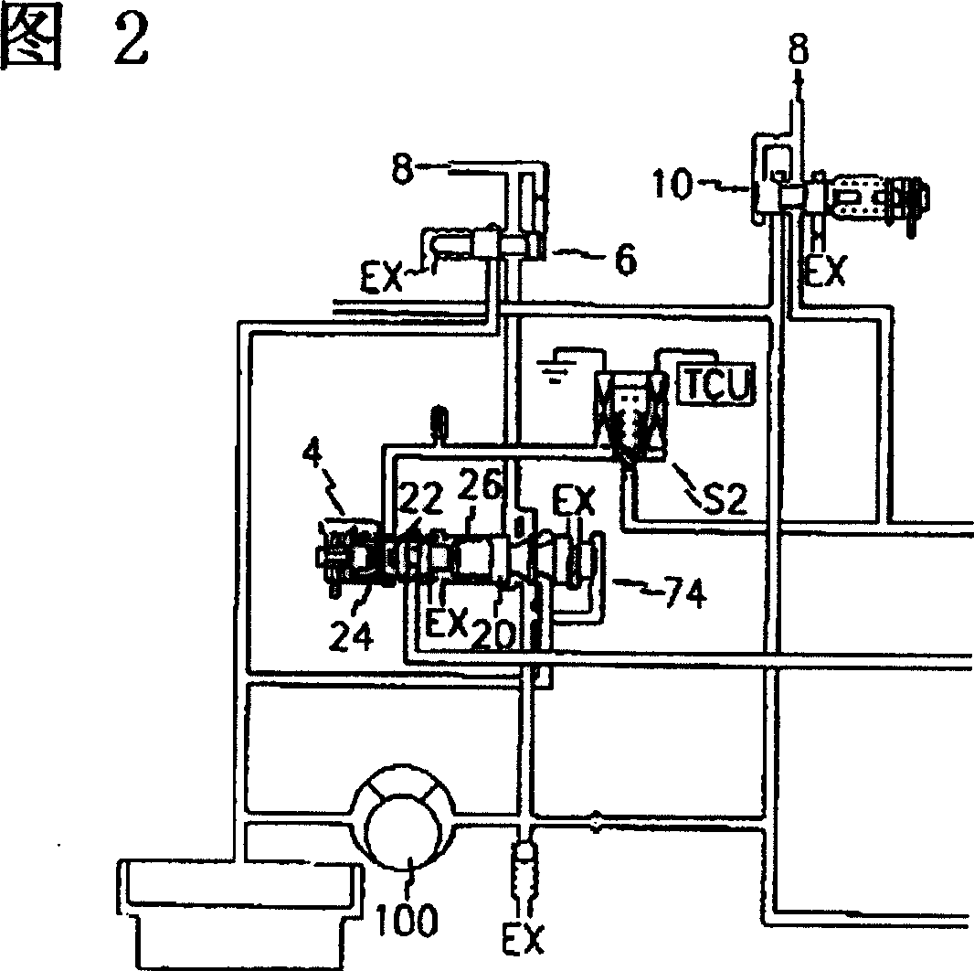
[0019] see figure 1 , the hydraulic pressure generated by the hydraulic pump 2 is adjusted through a regulating valve 4 so as to have a predetermined delivery pipe pressure. On the one hand, the regulated delivery line pressure is regulated by a torque converter control valve 6, which is then supplied to a damper clutch valve 8 under the control of the damper clutch solenoid valve S1, and on the other hand, by a pressure reducing valve 10. Partially reduce the delivery line pressure in order to supply it to the damping clutch control valve 8 or to the friction elements via the hydraulic control part and the hydraulic distribution part, which are switched by the driver actuating a manual valve 12 Its orifice, in order to lead the pressure to the required delivery pipe.

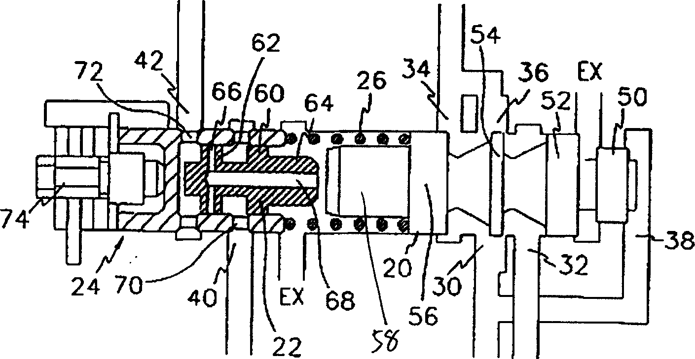
[0020] The regulating valve 4 communicates with the pressure reduci...


PUM


Abstract

A line pressure control system of an automatic transmission includes a hydraulic pump for generating hydraulic pressure, a regulator valve for adjusting the pressure from the hydraulic pump to a predetermined level, a torque converter control valve for adjusting a partial pressure from the regulator valve, a damper clutch valve receiving the adjusted pressure from the torque converter control valve for feeding the pressure to a damper clutch, a damper clutch solenoid valve for controlling the damper clutch valve, a reducing valve for reducing a partial pressure from the regulator valve and then supplying the reduced pressure to the damper clutch control valve, wherein the regulator valve includes a valve body, first and second valve spools coaxially inserted into the valve body, a sleeve encapsulating the second valve spool, and a coil spring interposed between the first and the second valve spools.

Description

technical field [0001] The invention relates to a hydraulic control system of an automatic transmission device, which can adjust the delivery pipe pressure of the hydraulic system. Background technique [0002] Generally, a conventional automatic transmission for vehicles includes a multi-stage gear transmission coupled to a torque converter and a plurality of friction elements hydraulically actuated to select a gear stage of the gear transmission. [0003] In such a hydraulic control system, hydraulic pressure generated by a hydraulic pump is selectively supplied to each friction element through a plurality of control valves, thus realizing automatic shifting according to a driving state of a vehicle and an engine adjustment opening. [0004] The above-mentioned hydraulic control system generally includes: a pressure regulating controller for controlling the hydraulic pressure generated by the hydraulic pump; manual and automatic shift controllers for selecting shift modes;...

Claims


Application Information

Patent Timeline
Patent Type & Authority Patents(China)
IPC IPC(8): F16H61/14F16H61/00
CPCF16H2061/0253F16H61/0021F16H61/14Y10T137/4245F16H61/04
Inventor 金泰均张在德朴钟述沈炫秀李瑨熙李昌郁
Owner HYUNDAI MOTOR CO LTD
Why Eureka
Try Eureka