Piezoelectric transformer
A technology of piezoelectric transformers and piezoelectric materials, applied in the field of piezoelectric transformers, can solve problems such as electric power limitations
- Summary
- Abstract
- Description
- Claims
- Application Information
AI Technical Summary
Problems solved by technology
Method used
Image

Examples
Embodiment approach 1
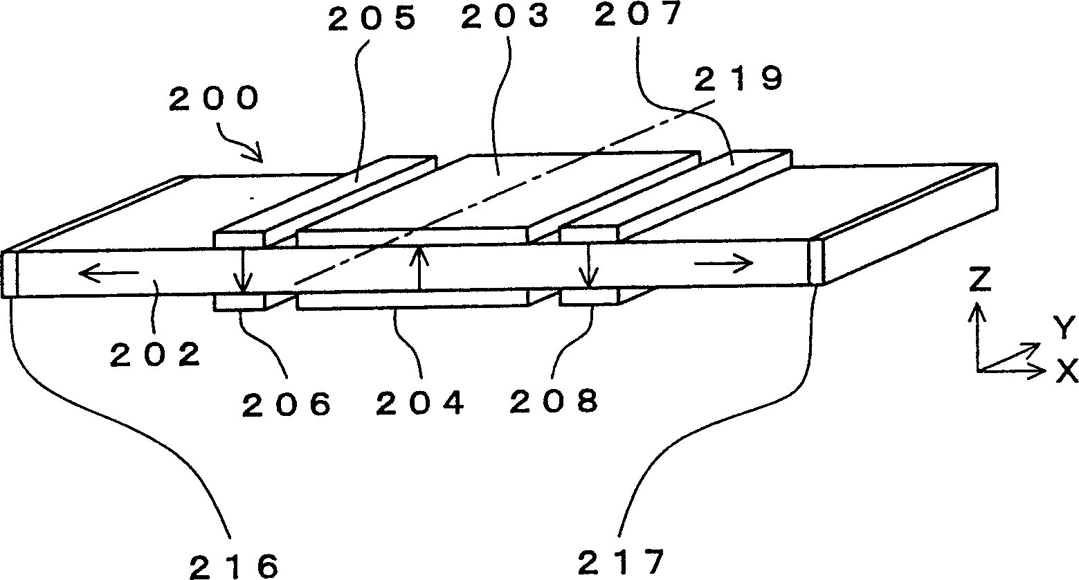
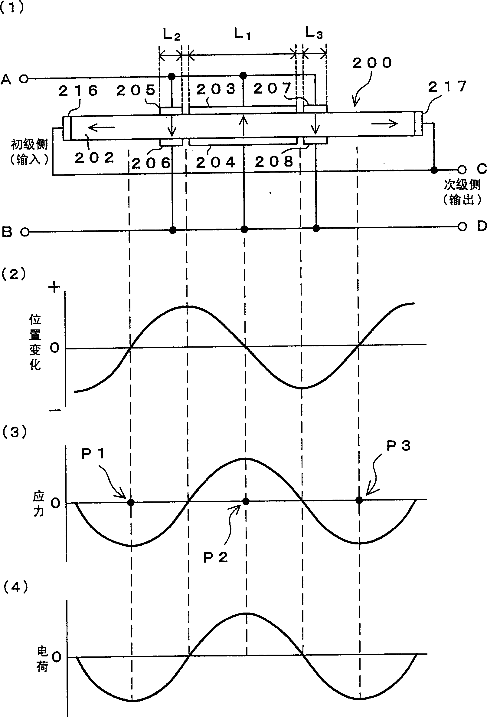
[0108] figure 1 is an axial side view of the 3λ / 2 vibration model piezoelectric transformer in Embodiment 1 of the present invention, figure 2 (1) is figure 1 Side view of the piezoelectric transformer shown. exist figure 1 with figure 2 (1) The medium voltage transformer 200 is composed of a rectangular plate 202 made of a piezoelectric material. first use figure 1 The shown Cartesian coordinate system defines the orientation of the rectangular plate 202 . The length direction, width direction and thickness direction of rectangular plate 202 refer to respectively figure 1 The x-axis direction, y-axis direction and z-axis direction in the Cartesian coordinate system. This applies to all voltage transformers described hereinafter. Also, in the following description, the length of one finger means the length in the longitudinal direction of the rectangular plate. The length in the width direction of the rectangular plate and the length in the thickness direction ...
Embodiment approach 2
[0131] Image 6 is an axial side view of a 3λ / 2 vibration model piezoelectric transformer in Embodiment 2 of the present invention, Figure 7 (1) is Image 6 Side view of the piezoelectric transformer shown. exist Image 6 with Figure 7 In (1), the piezoelectric transformer 220 is composed of a rectangular plate 222 made of a piezoelectric material. Primary-side (input-side) electrodes are formed on both main faces perpendicular to the thickness direction of the rectangular plate 222 . Of these two main surfaces, a primary side electrode consisting of electrode 223 , electrode 225 , and electrode 227 is formed on one main surface, and a primary side electrode composed of electrode 224 , electrode 226 , and electrode 228 is formed on the other main surface. Furthermore, the respective centerlines of the electrodes 223 and 224 may be formed to substantially coincide with the centerline 239 of the rectangular plate 222 . The electrodes 223 and 224, the electrodes 225 and 2...
Embodiment approach 3
[0145] Figure 8 is an axial side view of the 3λ / 2 vibration model piezoelectric transformer in Embodiment 3 of the present invention, Figure 9 (1) is Figure 8 Side view of the piezoelectric transformer shown. exist Figure 8 with Figure 9 In (1), the piezoelectric transformer 240 is composed of a rectangular plate 242 made of a piezoelectric material. Near the center of the rectangular plate 242 in the lengthwise direction, a primary-side (input-side) electrode composed of a plurality of electrodes is formed along the lengthwise direction and the thickness direction of the rectangular plate 242 . This is a laminated structure in which a piezoelectric body layer made of a piezoelectric material such as piezoelectric ceramics and an internal electrode layer made of a metal material are laminated in the thickness direction of the rectangular plate 242 .
[0146] Figure 9In (1), five piezoelectric layers and four electrode layers are formed between the primary-side elec...
PUM
 Abstract
Description
Claims
Application Information
 - R&D
- Intellectual Property
- Life Sciences
- Materials
- Tech Scout
- Unparalleled Data Quality
- Higher Quality Content
- 60% Fewer Hallucinations
Browse by: Latest US Patents, China's latest patents, Technical Efficacy Thesaurus, Application Domain, Technology Topic, Popular Technical Reports.
© 2025 PatSnap. All rights reserved.Legal|Privacy policy|Modern Slavery Act Transparency Statement|Sitemap|About US| Contact US: help@patsnap.com