
Optical transmission receiver module and producing method, electronic device using with the same module

一种光接收元件、接收器的技术,应用在光学元件、电固体器件、光学等方向,能够解决光发射元件1103和光接收元件1105光学位置光学系统优化、损坏光纤分隔板等问题

Inactive Publication Date: 2006-02-22
SHARP KK
View PDF2 Cites 0 Cited by
  • Summary
  • Abstract
  • Description
  • Claims
  • Application Information

AI Technical Summary

Problems solved by technology

Therefore, similar to the first conventional optical transceiver module, there is a problem that the end face 1102 of the optical fiber and / or the partition plate 1111 are damaged.
Furthermore, in this second optical transceiver module, the light-emitting element 1103 and the light-receiving element 1105 are mounted on the same substrate 1109, but the optical positions of the light-emitting element 1103 and the light-receiving element 1105 are not relative to those having the partition plate 1111. The optical system is optimized

Method used


Image

  • Optical transmission receiver module and producing method, electronic device using with the same module
  • Optical transmission receiver module and producing method, electronic device using with the same module
  • Optical transmission receiver module and producing method, electronic device using with the same module

Examples


Embodiment Construction

[0084] Next, the optical transceiver module and electronic equipment of the present invention will be described based on the embodiments of the present invention shown in the drawings.

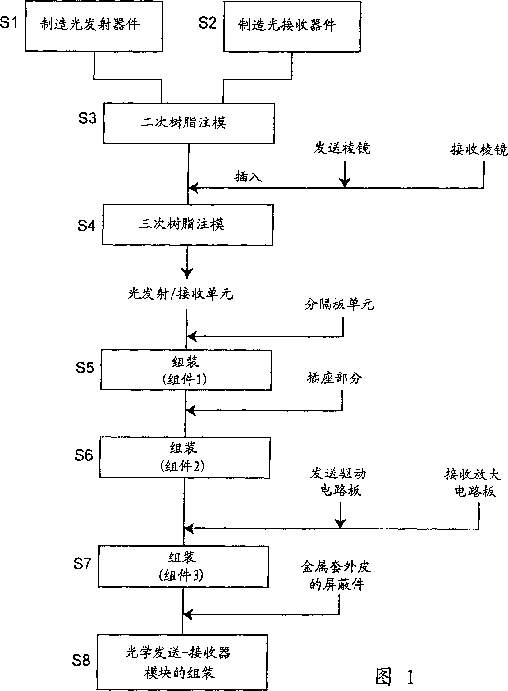
[0085] In explaining the embodiments of the present invention, an outline of a method of manufacturing the optical transceiver module of the present invention will be first described, and then details of the configuration of the optical transceiver module and its manufacturing method will be described.

[0086] FIG. 1 is a flowchart showing a method of manufacturing the optical transceiver module of this embodiment. The optical transceiver module of this embodiment is manufactured according to the flowchart of FIG. 1 .

[0087] First, in step S1, a light-emitting device is manufactured by encapsulating a light-emitting element through transfer molding.

[0088] Next, in step S2, a light-receiving device is manufactured by encapsulating the light-receiving element by transfer molding.

[0089...


PUM


Abstract

In an optical transmitter-receiver module for performing optical transmission and reception by using a single-core optical fiber, a light-tight partition plate unit 506 for separation between an optical path of a transmission signal light and an optical path of a reception signal light is held between a jack section 508 for detachably holding an optical plug 240 and a light emitting / receiving unit 505 having an LED 514 and a PD 515 positioned and fixed in place and molded in one piece.

Description

technical field [0001] The present invention relates to an optical transceiver module and electronics for a single-core bidirectional optical transceiver system capable of transmitting and receiving with a single-core optical fiber. In particular, the present invention relates to a digital communication system capable of high-speed transmission such as IEEE1394 (Institute of Electrical and Electronics Engineers 1394) and USB (Universal Serial Bus) 2.0. The invention also relates to a method of manufacturing an optical transceiver module. Background technique [0002] Conventionally, as the first optical transceiver module, one is described in Japanese Patent Laid-Open No. 2001-116961. In this optical transceiver module, full-duplex communication is achieved by using shielding plates to reduce electrical crosstalk and simultaneously using opaque partitions to reduce optical crosstalk. The plate abuts against the end face of the optical fiber to separate the light emitting d...

Claims


Application Information

Patent Timeline
Patent Type & Authority Patents(China)
IPC IPC(8): G02B6/42G02B6/34H04B10/12G02B6/43H01L23/48H01L31/0232H01L31/12H01L33/00H01L33/58
CPCG02B6/43G02B6/4246H01L2224/48247G02B6/4204H01L2224/45144G02B6/4219H01L2924/3025H01L2224/49171H01L2924/181H01L2924/00H01L2924/00012
Inventor 大江信之名仓和人曾根基树
Owner SHARP KK
Features
  • Generate Ideas
  • Intellectual Property
  • Life Sciences
  • Materials
  • Tech Scout
  • Unparalleled Data Quality
  • Higher Quality Content
  • 60% Fewer Hallucinations
Learn More