Method and instrument for profiling magnetic flux

A magnetic flux density, stator technology, applied in the direction of electrical components, electromechanical devices, windings, etc., can solve the problems of lack of manufacturing process and connection process, weak electrical characteristics, etc., to reduce size and weight, reduce heating problems, and improve efficiency Effect

Inactive Publication Date: 2000-05-31
贾默・阿拉梅基
View PDF1 Cites 7 Cited by
  • Summary
  • Abstract
  • Description
  • Claims
  • Application Information

AI Technical Summary

Problems solved by technology

But the problem is that compared with other methods, its electrical characteristi

Method used


Image

  • Method and instrument for profiling magnetic flux
  • Method and instrument for profiling magnetic flux
  • Method and instrument for profiling magnetic flux

Examples


Embodiment approach

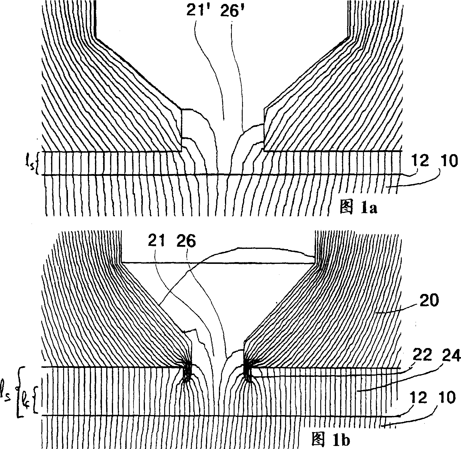
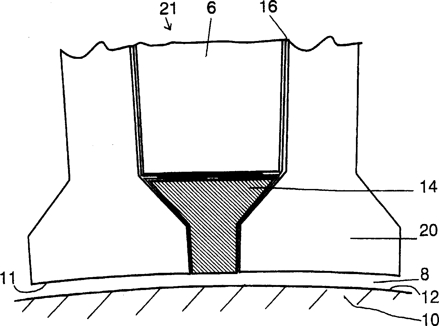
[0015] According to a preferred embodiment of the invention, the electric machine comprises a rotor means and a stator means surrounding the rotor means, and the stator means has a plurality of radially extending slots. At least some of the slots contain slot-lock elements characterized in that they extend within the slots around the rotor bore of the stator assembly and that the relative permeability of the slot-lock elements (µ r ) is better, μ r Greater than 5, in addition, its saturation magnetic flux density is at least 0.2T.

[0016] Preferably, the resistivity of the material is as high as possible, and preferably its resistivity substantially matches that of an insulator. In addition, the material should have sufficient heat-resistant strength.

[0017] According to the method of the invention, a stator lock is installed in the stator slot of the motor. This stator lock extends in the slot to around the rotor hole of the stator device, and the material it chooses ha...


PUM

PropertyMeasurementUnit
Saturation flux densityaaaaaaaaaa

Abstract

An electric machine according to the invention comprises a rotor means (10) and a stator means (20) surrounding the rotor means having radially extending slots (21). Slot lock components (14) are provided in at least some of said slots. The slot lock extends in said slot essentially to the periphery of the rotor bore of the stator means. The relative permeability ( u r) and the saturated flux density of the slot lock means is essentially good. In the inventive method the density of magnetic flux effecting on the rotor means surface is made more uniform by slot lock components described above.

Description

field of invention [0001] According to the preamble of claim 1, the invention relates to a method for an electrical machine, in particular, which method incorporates a slot lock device in a stator slot. Furthermore, according to the preamble of claim 5, the invention also relates to an electric motor with a dedicated slot lock. According to the preamble of claim 13, the invention also relates to a slot lock for an electric motor. Background of the invention [0002] In electric machines, especially those known as solid rotor machines, there are losses at the surface of the rotor caused by harmonics of the magnetic flux generated between the rotor and the stator. Losses reduce the efficiency of the motor and create overheating problems. Figure 1a schematically shows the shape of the magnetic flux density and its non-uniform distribution in a prior art motor. [0003] Referring to the simplified figure 1b, the above-mentioned problems can be solved by adding a special stato...

Claims


Application Information

Patent Timeline
IPC IPC(8): H02K3/493
CPCH02K3/493Y02P80/30
Inventor 贾默·阿拉梅基J·皮尔赫内J·胡庞内
Owner 贾默・阿拉梅基
Why Eureka
Try Eureka