Light pulse arbitary time shaping device

An arbitrary time, shaping device technology, applied in optics, optical components, nonlinear optics, etc., can solve problems such as high cost and complex structure, and achieve the effect of low cost, simple structural unit and high reliability

Inactive Publication Date: 2006-05-17
SHANGHAI INST OF OPTICS & FINE MECHANICS CHINESE ACAD OF SCI
View PDF0 Cites 0 Cited by
  • Summary
  • Abstract
  • Description
  • Claims
  • Application Information

AI Technical Summary

Problems solved by technology

[0007] Replacing the Pockels cell with an integrated optical modulator is structurally more complex and costly

Method used


Image

  • Light pulse arbitary time shaping device
  • Light pulse arbitary time shaping device
  • Light pulse arbitary time shaping device

Examples


Embodiment Construction

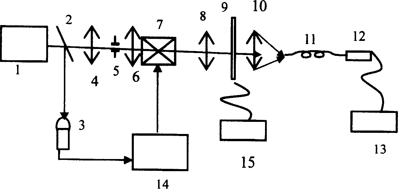
[0030] see first figure 1 , figure 1 It is a schematic diagram of the optical path of the optical pulse shaping device at any time of the present invention. It can be seen from the figure that the light pulse shaping device at any time of the present invention has the following structure: a beam splitter 2 and a first convex lens are sequentially arranged on the main axis of the output beam of the main oscillator 1 4, pinhole diaphragm 5, second convex lens 6, electro-optic deflector 7, third convex lens 8, liquid crystal spatial light modulator 9, fourth convex lens 10, and the first convex lens 4, pinhole diaphragm 5 and The second convex lens 6 forms a 4F system, the electro-optical deflector 7 is located on the front focal plane of the third convex lens 8, and the liquid crystal spatial light modulator 9 is located on the rear focal plane of the third convex lens 8, and the liquid crystal spatial light modulator 9 and Computer 15 is connected;

[0031] The beam splitter ...


PUM


Abstract

A device for shaping optical pulses at any time, which comprises a beam splitter, a first convex lens, a small hole diaphragm, a second convex lens, a photoelectric deflector, a third convex lens, and a liquid crystal spatial light modulation device in sequence on the main axis of the output beam of the main oscillator. and the fourth convex lens, and the first convex lens, aperture stop and second convex lens constitute a 4F system, the photoelectric deflector is located on the front focal plane of the third convex lens, and the liquid crystal spatial light modulator is located on the third convex lens On the rear focal plane, the liquid crystal spatial light modulator is connected with a computer; there is a PIN tube in the reflected light direction of the beam splitter, and the PIN tube is connected to the high-voltage trigger circuit of the photoelectric deflector; the focus of the fourth convex lens and The input ends of the single-mode optical fiber are overlapped, the output end of the single-mode optical fiber is connected to a high-current tube, and the output end of the high-current tube is connected to an oscilloscope. The invention can realize light pulse output of any shape, and has the characteristics of simple structure, convenient adjustment and the like.

Description

technical field [0001] The invention relates to nanosecond pulses, and relates to an optical pulse time shaping device, which can realize the output of nanosecond level arbitrary shaped time shaped optical pulses. Background technique [0002] Inertial confinement fusion requires that the laser pulse output by the driving source must have a suitable pulse shape. Arbitrary shape time-shaping output technology is a key to the front-end section of the driver. The main methods currently used are: pulse stacking, block Pockels cell high-voltage clipping, integrated optical modulation, etc. [0003] 1. Pulse stacking (GEKKO_XII): This device uses a fiber optic pulse stacker to synthesize multiple unit pulses into complex-shaped optical pulses in a stacking manner. Although the combination method is very flexible, there are many units and the structure is complex, which affects the stability; [0004] 2. Blocky Pockels cell high voltage clipping: [0005] Using photoconductive ...

Claims


Application Information

Patent Timeline
Patent Type & Authority Patents(China)
IPC IPC(8): G02B27/10G02B27/28G02F1/01
Inventor 康俊陈绍和韦辉张伟马忠林
Owner SHANGHAI INST OF OPTICS & FINE MECHANICS CHINESE ACAD OF SCI
Why Eureka
Try Eureka