Image recording equipment

A technology of image recording and image signal, applied in the field of image recording device

Inactive Publication Date: 2006-05-17
SANYO ELECTRIC CO LTD
View PDF0 Cites 0 Cited by
  • Summary
  • Abstract
  • Description
  • Claims
  • Application Information

AI Technical Summary

Problems solved by technology

[0003] However, writing of new image signals to the buffer memory is prohibited while the recording process is being performed.
If the recording medium is a disk recording medium such as a magneto-optical disk, there is a case where the recording process of one image signal takes about two seconds. Therefore, if the number of continuous shooting is 40 times, the image signals from 40 are stored in the buffer. It takes about 80 seconds for the memory to be ready for the next shot

Method used


Image

  • Image recording equipment
  • Image recording equipment
  • Image recording equipment

Examples


Embodiment Construction

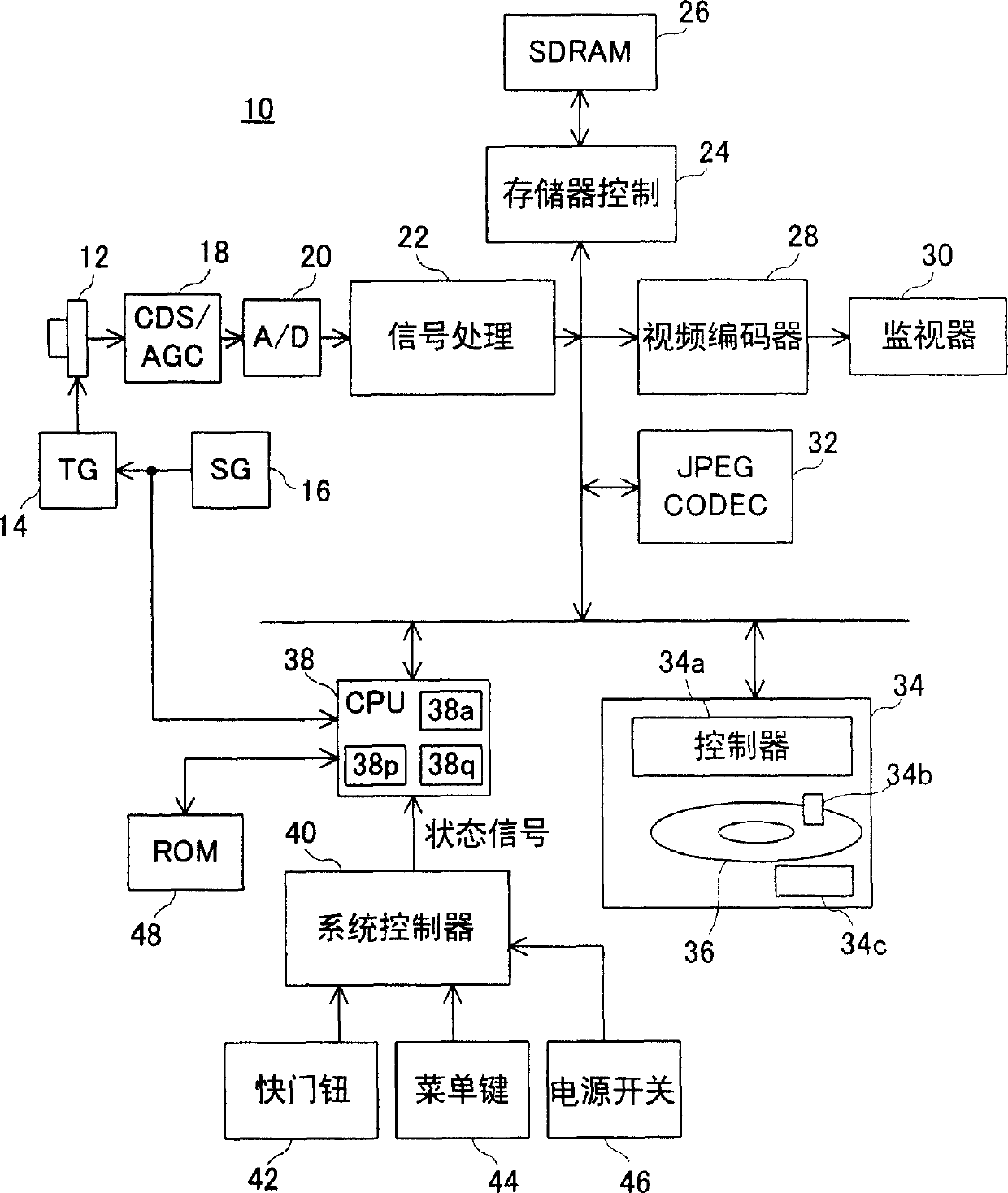
[0031] Referring to FIG. 1 , a digital camera 10 of the present embodiment includes an image sensor 12 . A color filter (not shown) is attached on the front surface of the image sensor 12 , and an optical image of an object is incident to the image sensor 12 through this color filter.

[0032] When the power supply 46 is turned on, the system controller 40 provides battery power (not shown) to the entire system and applies corresponding status signals to the CPU 38 . The CPU 38 instructs the TG (Timing Generator) 14 to perform shooting according to the frame rate, for example, 15 fps, and applies predetermined processing instructions to the signal processing circuit 22 and the video encoder 28 .

[0033] The TG 14 generates a timing signal based on a vertical synchronization signal and a horizontal synchronization signal output from an SG (Signal Generator) 16, and drives the image sensor 12 according to a cluster scanning system. A photographic signal (charge) is output from...


PUM


Abstract

The digital camera (10) includes an SDRAM (26). When 40 frames of image signals were gathered in SDRAM (26), in the data area of ​​magneto-optical disc (36), create the combination file that comprises 40 frames of image signals, and the FAT information of combination file is written into the FAT of magneto-optical disc (36) in the district. When meeting the predetermined condition, the image data of the combined file is read out by each frame, and an image file comprising the read image data is created in the data area of ​​the magneto-optical disk (36), and the FAT information of the image file is written into The FAT area of ​​the magneto-optical disk (36). Repeat this process 40 times, after which the combined file is deleted.

Description

technical field [0001] The present invention relates to an image recording device, and in particular to an image recording device which is suitable for a digital camera and records image signals on a recording medium through a buffer memory. Background technique [0002] In a digital camera, if a continuous shooting mode (continuous shooting mode) is selected, a subject is shot at a rate of one shot every 1 / 15 second, and shot image signals are stored in a buffer memory. Once a predetermined number of shots are completed, a recording process of a large number of image signals accumulated on the buffer memory is performed. Specifically, a large number of image files respectively containing a large number of image signals are formed in the data area of ​​the recording medium, and file management information for respectively managing the large number of image files is written in the management area of ​​the recording medium. [0003] However, writing of new image signals into ...

Claims


Application Information

Patent Timeline
Patent Type & Authority Patents(China)
IPC IPC(8): H04N5/91H04N5/907H04N5/765G11B27/00G11B27/034G11B27/036G11B27/32H04N1/21H04N5/225H04N5/781H04N5/85H04N5/937
CPCG11B27/034G11B27/036G11B27/329G11B2220/2525H04N1/2112H04N1/2141H04N1/32112H04N2101/00H04N2201/218H04N2201/3247H04N2201/3277H04N5/907
Inventor 郭顺也
Owner SANYO ELECTRIC CO LTD
Why Eureka
Try Eureka