
Valve stem sealing component for IC engine

A technology for valve stems and internal combustion engines, which is applied in the direction of engine sealing, engine sealing devices, engine components, etc., and can solve problems such as unsatisfactory implementation forms

Inactive Publication Date: 2006-06-21
CARL FREUDENBERG KG
View PDF2 Cites 0 Cited by
  • Summary
  • Abstract
  • Description
  • Claims
  • Application Information

AI Technical Summary

Problems solved by technology

But this form of implementation is not very satisfactory

Method used


Image

  • Valve stem sealing component for IC engine
  • Valve stem sealing component for IC engine
  • Valve stem sealing component for IC engine

Examples


Embodiment Construction

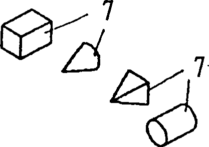
[0014] The valve stem seal 1 consists of a support element 2 made of sheet metal, to which a sealing element 3 is fastened. The sealing element 3 is made of polymer material. It has a static seal 4 with a ring-shaped lug, with which the sealing element is placed on the valve stem guide, not shown, and the sealing element 3 has a sealing lip 5 at its upper end, which is attached to the valve in the assembled state. on the pole. Furthermore, the sealing lip 5 can also be compressed by means of an annular clamping spring 6 . On the sealing lip 5 there are a large number of projections 7 whose inner diameter is smaller than the inner diameter of the sealing lip 5 when viewed relative to the valve stem axis. The protrusions 7 can be sprayed (injected) on the sealing lip 5 individually, or directly pressed together. They can consist of a less wear-resistant material than the sealing lip 5 and / or of the same material as the sealing lip.

[0015] The protrusions 7 may be conical a...


PUM


Abstract

A shaft seal for an IC engine has the flexible sealing lip shaped with a number or protuberances which lift the lip slightly and establishes a set amount of flow of lubricant. The protuberances are evenly spaced and have a set rate of wear to ensure that the sealing lip beds down onto the shaft. The protuberances are conical or linear and are made of any suitable material with the required wear characteristics. The inner diameter of the protuberances is less than the shaft diameter.

Description

technical field [0001] The invention relates to a valve stem seal for an internal combustion engine having at least one sealing lip of elastomer material surrounding the valve stem. [0002] One problem with valve stem seals is adequately feeding the valve stem with lubricating oil. The amount of lubricating oil should be metered here as precisely as possible, since too little lubricating oil or too much lubricating oil is disadvantageous. Background technique [0003] One possibility for supplying the valve stem with lubricating oil is shown in US 4.125.265. There, a seal is fastened to the valve stem guide (guide), which has two sealing lips which surround an annular chamber for oil storage. Through the axial movement of the valve stem, a pumping action is generated, so that the lubricating oil reaches between the valve stem and the valve stem guide. However, this lubricating or sealing effect is not very satisfactory. [0004] Utility model G9000671.2 proposes another...

Claims


Application Information

Patent Timeline
IPC IPC(8): F01L3/08F01M9/10F16J15/32F02F11/00F16J15/324F16J15/3244F16K1/226
CPCF01L3/08F01L2810/02F16J15/324F16J15/3244F01L2301/00
Inventor M·阿罗拉
Owner CARL FREUDENBERG KG
Learn More