
Waveform controller for vibro-bench

A technology of control unit and control method, applied in the direction of automatic control, automatic control, automatic controller, etc.

Inactive Publication Date: 2006-07-12
MITSUBISHI HEAVY IND LTD
View PDF0 Cites 0 Cited by
  • Summary
  • Abstract
  • Description
  • Claims
  • Application Information

AI Technical Summary

Problems solved by technology

And further, there is the problem that it is impossible for a waveform control unit using a predetermined shaker characteristic during excitation to follow a single blast failure test like the

Method used


Image

  • Waveform controller for vibro-bench
  • Waveform controller for vibro-bench
  • Waveform controller for vibro-bench

Examples


Embodiment Construction

[0046] DETAILED DESCRIPTION OF THE PREFERRED EMBODIMENTS Preferred embodiments of the present invention will be described below with reference to the accompanying drawings. However, these examples do not limit the technical scope of the present invention. Incidentally, in the drawings, descriptions are given by attaching the same reference numerals or characters to the same similar objects.

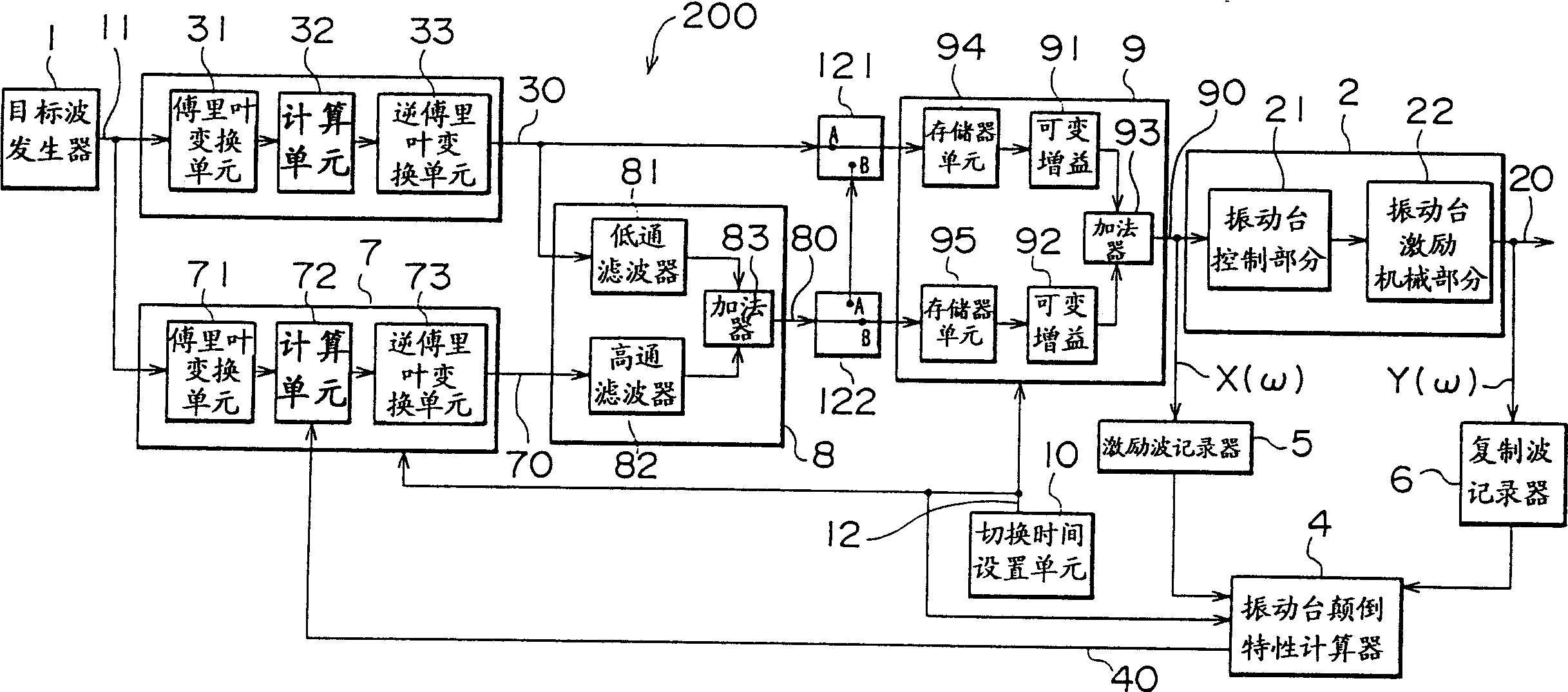
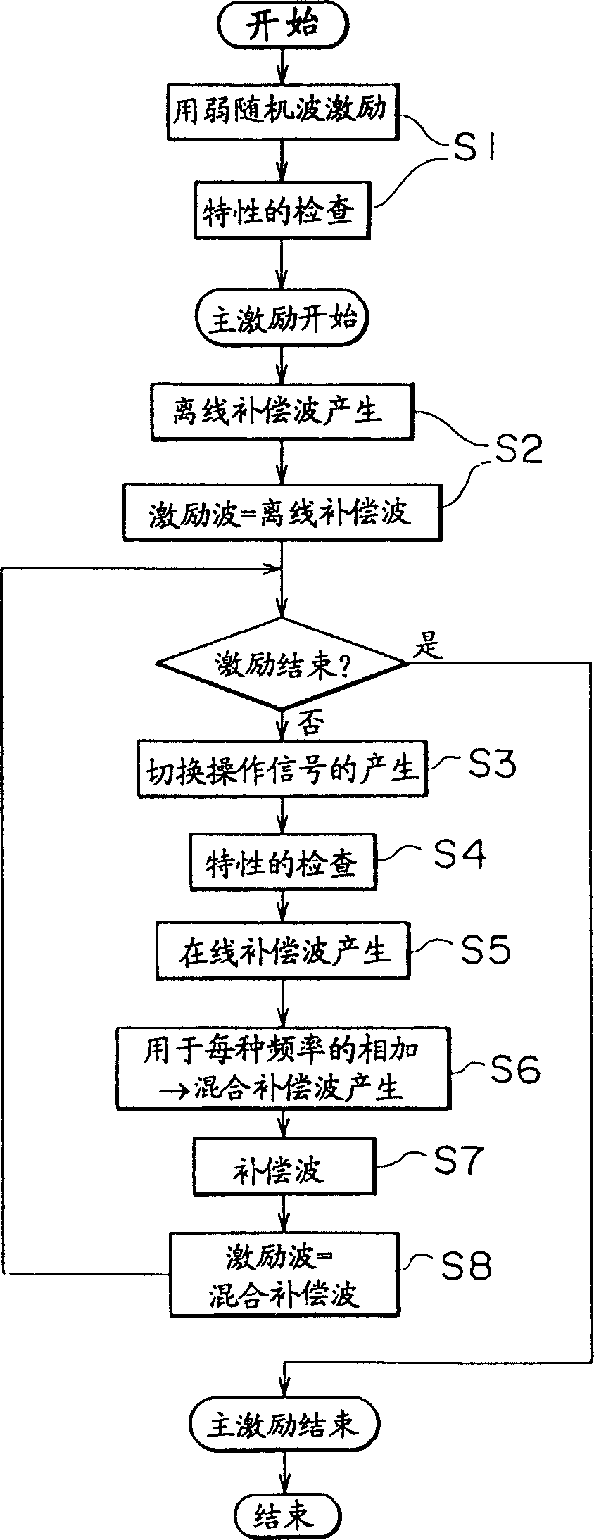
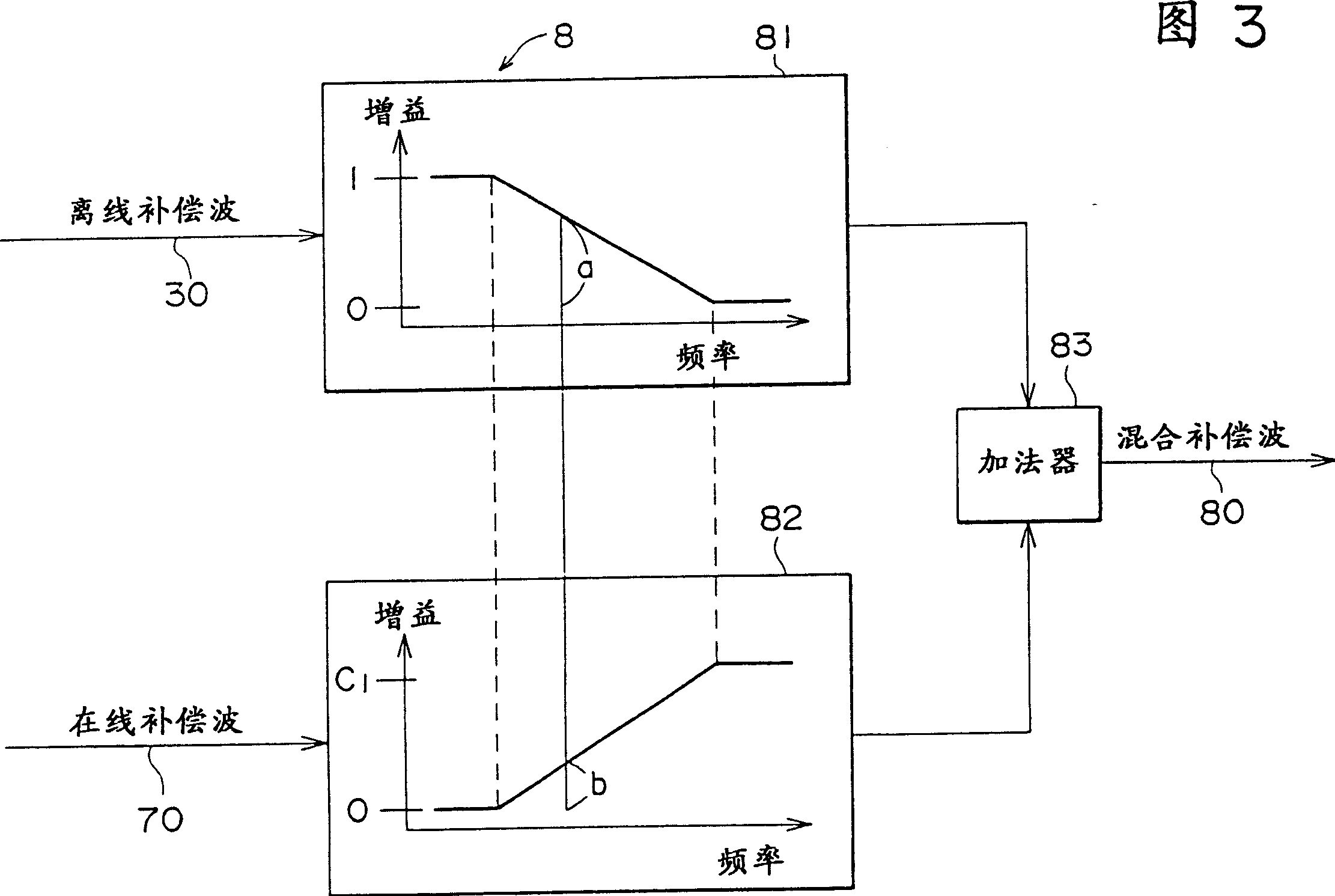
[0047] figure 1 is a block diagram showing a first embodiment of the waveform control unit to which the present invention is applied. A waveform control unit 200 according to the first embodiment of the present invention is a unit in which, for each time, the excitation period preset before the excitation, determines the inverse characteristic of the vibrating table at that time, and switches the excitation wave to This inverse characteristic produces a compensating wave. That is, it is a unit in which on-line compensation is performed at each setting moment during excitation.

[004...


PUM


Abstract

A waveform control unit of a vibrating table comprises: an off-line compensation wave generator which generates an off-line compensation wave on the basis of the inverse characteristic of the vibrating table determined before performing an excitation and a target wave; and an on-line compensation wave generator which generates an on-line compensation wave on the basis of the inverse characteristic of the vibrating table during the excitation determined on the basis of the data of an excitation wave and a reproduced wave during the excitation and the target wave, and it switches the excitation wave to a mixed compensation wave based on the on-line compensation wave from the off-line compensation wave, during the excitation.

Description

technical field [0001] The present invention relates to a vibrating device applicable to a vibrating table and a wave front control unit, and to a real-time adaptive waveform control device and method capable of generating target waves, and reproduced waves coincide with each other by a single excitation. Background technique [0002] Previously, in order to check the condition, strength, etc. of structures during, for example, earthquakes, various types of vibration tests have been conducted, and for this purpose, vibration units have been used. Figure 12 Schematic representation of the configuration of this type of vibration unit. This vibrating unit has: a vibrating table 2 vibrating with a test piece 223 of an object to be tested mounted thereon; and a waveform control unit 100 controlling the waveform of the vibration. Also, the above-mentioned vibrating table 2 is provided with: a vibrating table control section 21 into which an output signal from the waveform control...

Claims


Application Information

Patent Timeline
Patent Type & Authority Patents(China)
IPC IPC(8): G05B11/00G05D19/00G01V1/36F16F15/02G01M7/02G05B13/02G05D19/02H02P25/02
CPCH02P25/027G01M7/022G05D19/02H02P25/032G01M7/02G01V1/36
Inventor 奥田幸人前川明宽广江隆治作野诚
Owner MITSUBISHI HEAVY IND LTD
Learn More