Conic-body for cathode-ray tube
A cathode ray and tube technology, applied in the direction of cathode ray tube/electron beam tube, cathode ray/electron beam tube shell/container, discharge tube, etc., can solve problems such as time delay and gap rise
- Summary
- Abstract
- Description
- Claims
- Application Information
AI Technical Summary
Problems solved by technology
Method used
Image
Examples
Embodiment Construction
[0018] Hereinafter, embodiments of the present invention will be described based on the drawings.
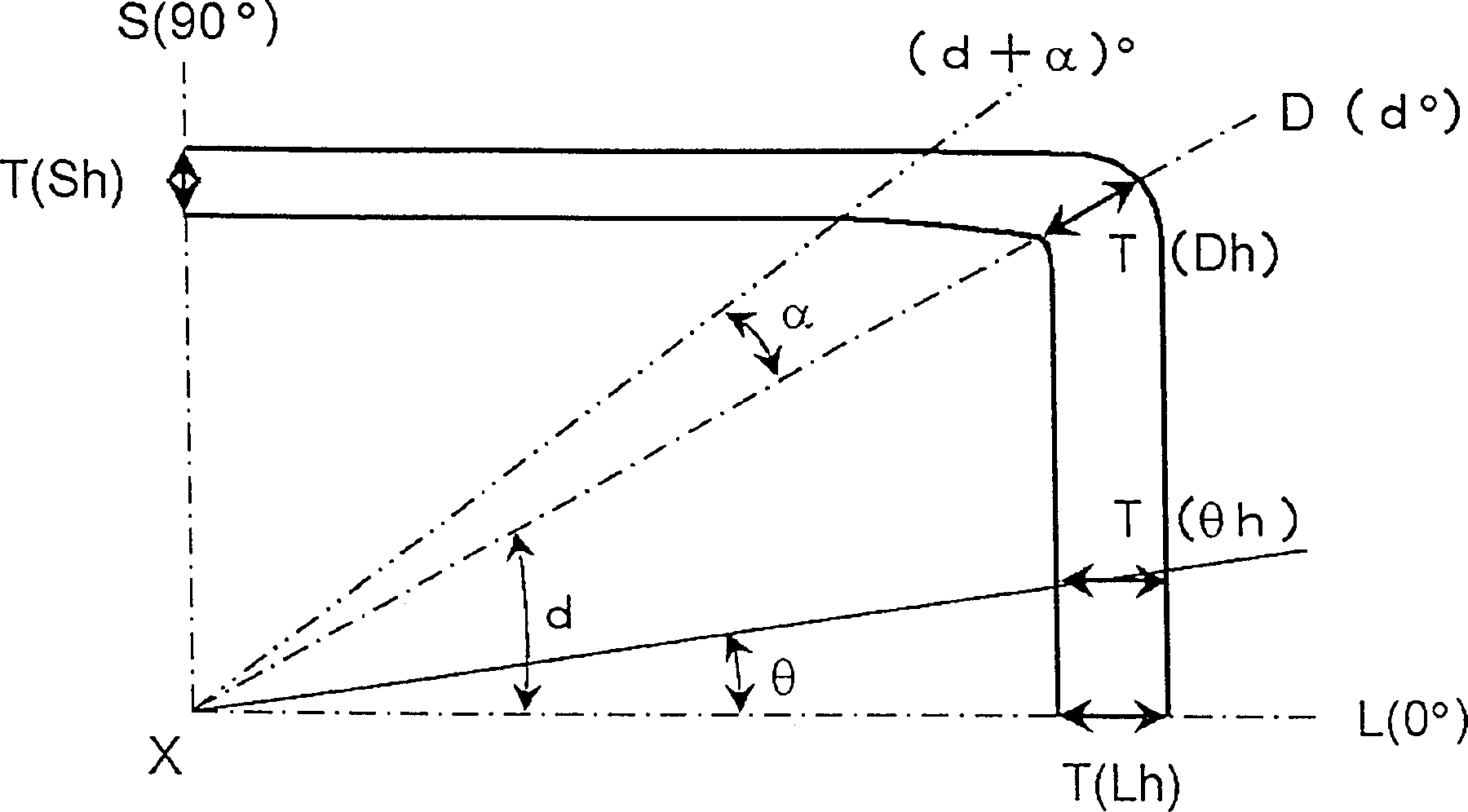
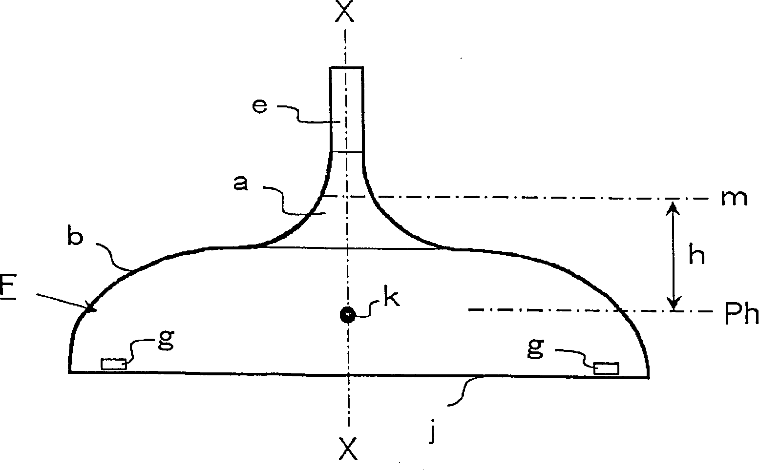
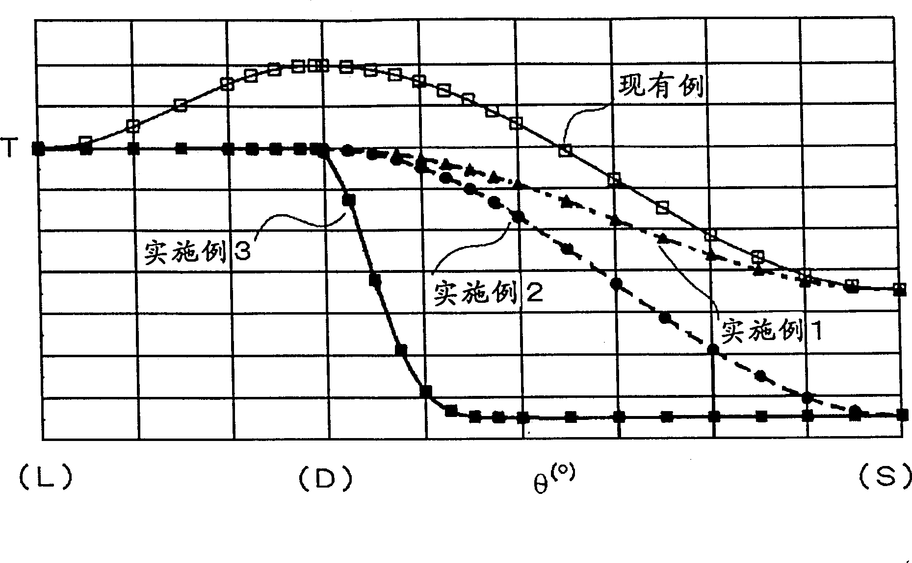
[0019] Fig. 1(A) is a cross-sectional view of a 90° portion (first quadrant) of a cone for a cathode ray tube at an arbitrary height h from the reference line for explaining the wall thickness distribution of the present invention, and Fig. 1(B) is the cone The side view of the whole body, figure 2 It is a graph showing an example of the thickness distribution state of the 90° portion (first quadrant) of the cone of the present invention.
[0020] As shown in Figure 1 (A) and Figure 1 (B), the cathode ray tube cone F is composed of a deflection system portion a on the small opening end side and a main body portion b on the large opening end side. The vertical cross-section is roughly quadrangular, with a long axis L, a short axis S, and a diagonal axis D. Except for the neck portion e, the deflection system portion a, the edge portion j, the anode buckle portion k, and the calibrati...
PUM
 Abstract
Description
Claims
Application Information
 - R&D
- Intellectual Property
- Life Sciences
- Materials
- Tech Scout
- Unparalleled Data Quality
- Higher Quality Content
- 60% Fewer Hallucinations
Browse by: Latest US Patents, China's latest patents, Technical Efficacy Thesaurus, Application Domain, Technology Topic, Popular Technical Reports.
© 2025 PatSnap. All rights reserved.Legal|Privacy policy|Modern Slavery Act Transparency Statement|Sitemap|About US| Contact US: help@patsnap.com


