
Device for pneumatic operation tool and pneumatic pliers with the device

A tool and piston technology, applied in the field of pneumatically operated devices, can solve the problems of discrete extrusion force, failure to maintain extrusion force, loss of extrusion force, etc., and achieve the effect of low dynamic friction

Inactive Publication Date: 2006-07-19
OETIKER SCHWEIZ AG
View PDF2 Cites 3 Cited by
  • Summary
  • Abstract
  • Description
  • Claims
  • Application Information

AI Technical Summary

Problems solved by technology

[0007] Designs known from the prior art have very discrete squeeze forces, generally do not maintain their squeeze force at the same pressure, and lose their squeeze force during their service life
Another disadvantage is that the known squeeze clamps are not maintenance-free

Method used


Image

  • Device for pneumatic operation tool and pneumatic pliers with the device
  • Device for pneumatic operation tool and pneumatic pliers with the device
  • Device for pneumatic operation tool and pneumatic pliers with the device

Examples


Embodiment Construction

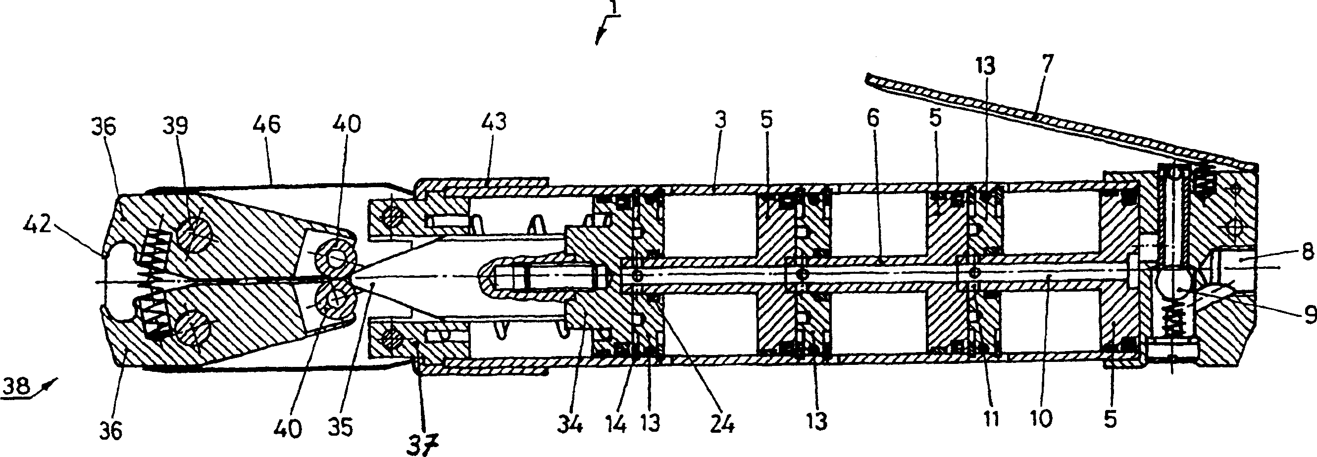
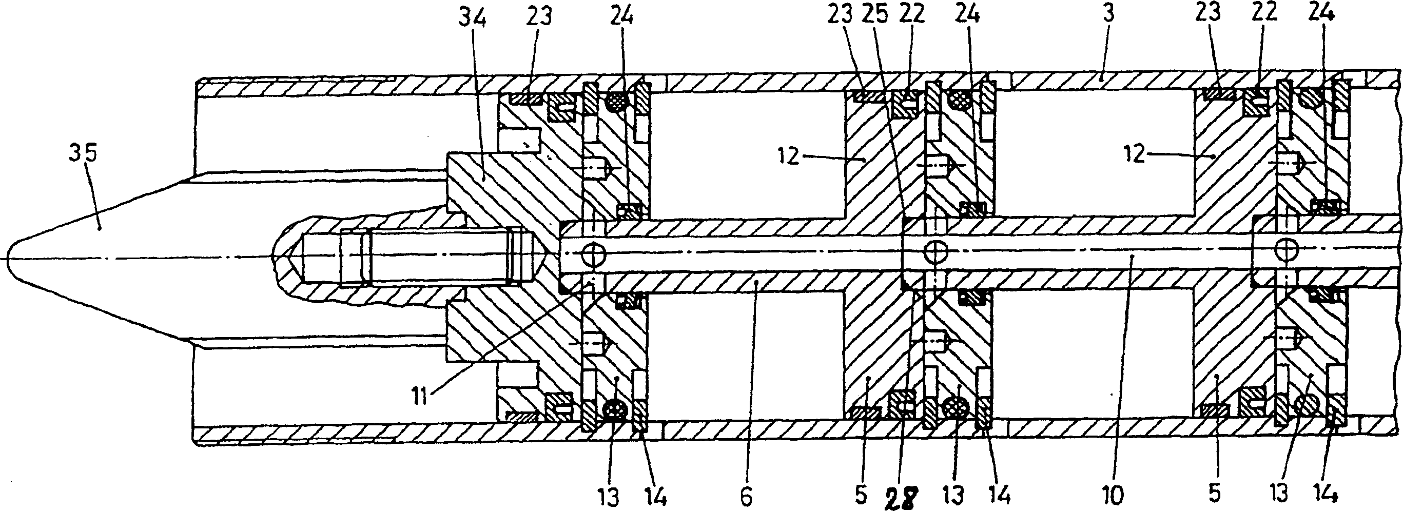
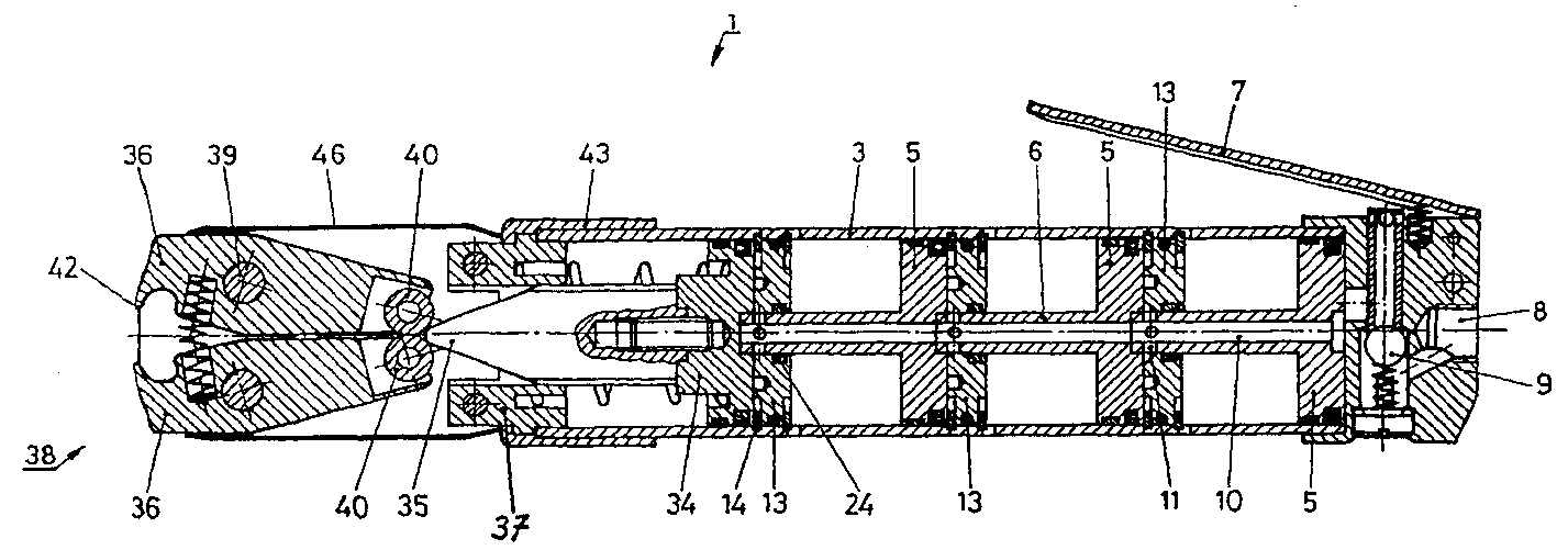
[0021] figure 1 A longitudinal sectional view is shown of a pneumatically actuatable and pressure-driven pliers 1 for mounting pipe clamps, hose clamps, retaining rings and the like. A plurality of pistons 5 arranged one behind the other in a row or series are arranged in a cylinder 3 . The advantage of such a series arrangement of pistons is that the force is increased by making it possible to generate displacement forces that are much greater than with a single piston. The reason is to increase the piston area.

[0022] A connection 8 is provided at the rear end of the manually actuatable pneumatic clamp, which connects the clamp to a pressure medium, for example compressed air, wherein the pressure medium can be supplied by means of a valve handle for actuating a valve 9 7 to open or ventilate. The individual pistons 5 have a through-bore 10 through the piston rod 6 for the passage of pressure medium. At the front end of the piston rod 6 there is provided a radially out...


PUM


Abstract

The implement, especially pneumatic tongs (1) has a cylinder (3) with one or more pneumatically operated pistons in a row. Each piston rod (6) in the cylinder cover (13) is sealed and guided by means of a seal (24) against the previous piston (5). Components (34,35) cooperate with the piston(s) for operating the implement. The pistons are supported by at least one piston-guide-belt towards the cylinder's inner wall.

Description

technical field [0001] The invention relates to a device for the pneumatic operation of a pressure-loaded tool and to a pneumatic clamp. Background technique [0002] Pneumatic clamps for squeezing and clamping retaining rings, pins, cable lugs, wire clamps and the like are well known. Pneumatic clamps are especially familiar in the automotive industry, where they are used to clamp retaining rings on pipe joints, joint shafts and the like when assembling inner tubes, bellows and the like. [0003] From DE 37 42 782 there is known a pressure medium clamp for spring clips which has a valve-controlled pressure medium connection and a wedge-shaped pusher. [0004] A similar pressure medium clamp is described in German utility model 8900250.4, in which there are a plurality of driving pistons arranged one behind the other in a series to increase the thrust, wherein the piston rod of each individual piston is in a cylinder wall inside guide. Likewise, DE 195 19543 and GM 295 09...

Claims


Application Information

Patent Timeline
Patent Type & Authority Patents(China)
IPC IPC(8): B25B7/12F15B15/14F15B11/036B25B27/14
CPCB25B27/146F15B2211/455B25B7/126F15B15/1438F15B11/0365F15B2211/7055F15B2211/41527F15B2211/40515F15B15/1442Y10T29/5377Y10T29/5383B25B7/12
Inventor P·温特哈尔特U·梅尔
Owner OETIKER SCHWEIZ AG
Learn More