Radiant flux fiber filter

A fiber filter, radiation flow technology, applied in the direction of gravity filter, filtration separation, loose filter material filter, etc., can solve the problems of increased packing density and filtration resistance, insufficient protection of water quality, and unfavorable protection of water quality. , to achieve the effect of reducing cleaning cost, reducing water filtration cost and good water quality

Inactive Publication Date: 2006-07-26
乔国章
View PDF3 Cites 0 Cited by
  • Summary
  • Abstract
  • Description
  • Claims
  • Application Information

AI Technical Summary

Problems solved by technology

The disadvantages of the above fiber filters are that when the flexible capsule is filled with water and expands, the capsule is often broken due to the lack of limit protection, and the reliability is poor; the filtration area is reduced due to the existence of the capsule; the effective area of ​​the filler along the filtration direction is gradually reduced due to the capsule. Decrease, forming a speed-up filter, which is not conducive to the protection of water quality
The thrust formed by the pressure head loss is used to realize the structure of the compressed fiber filler. When the water flow velocity fluctuates, the increase of the water head loss will cause the density of the filler and the filtration resistance to increase, thereby affecting the filtration effect and shortening the working cycle. Flow, not ideal for protecting water quality
Moreover, in order to increase the water filtration capacity of the above-mentioned various filters, the diameter of the container must be increased, thereby increasing the floor space.

Method used


Image

  • Radiant flux fiber filter
  • Radiant flux fiber filter
  • Radiant flux fiber filter

Examples


Embodiment 1

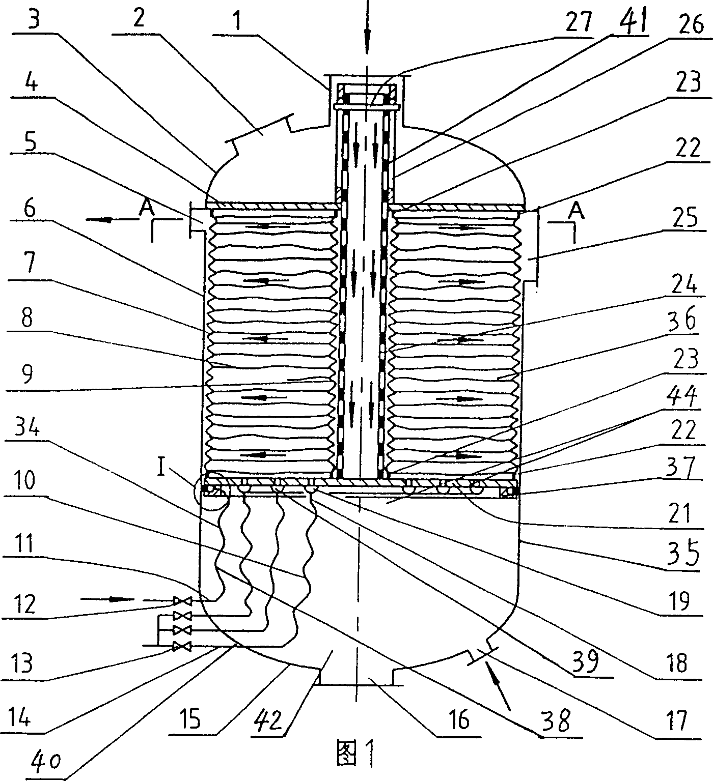
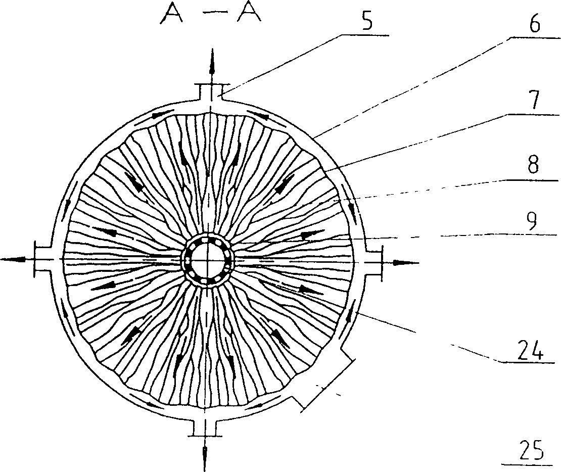
[0023] Embodiment 1: Referring to Figures 1 and 2, the container 35 of the radial flow fiber filter is composed of upper and lower heads 3, 15 and cylinder 6 welded. A water inlet 1 and a manhole 2 are provided on the upper head 3 of the container 35 , four water outlets 5 and manholes 25 are provided on the cylinder 6 , and a water inlet 17 and a manhole 16 are provided on the lower head 15 . The fixed plate 4 is welded on the upper end of the cylinder body 6 in the container 35, the upper center of the fixed plate 4 is vertically welded or connected with a guide pipe 26 with a flange, and the porous water distribution pipe 24 is welded with the floating plate 21 or connected with a flange. Installed in the guide pipe 26, and placed in the symmetrical long slot 41 provided on the guide pipe 26 through the limit pin 27 that is installed on the porous water distribution pipe 24, the water in the container 35 cannot pass through the floating plate 21 Up and down circulation.

...

Embodiment 2

[0026] Embodiment 2: Referring to FIG. 9, the internal structure of this radial flow fiber filter is the inversion of the internal structure of the radial flow fiber filter in Embodiment 1, and its structural principle is the same. It is just that in the container 35 of the radial flow fiber filter of embodiment 2, the upper floating disc 21 and the lower fixed disc 4 are installed, and the gas distribution device 39 is placed on the fixed disc 4, and the gas distribution holes and annular distribution holes provided on the floating disc 21 of the embodiment 1 are removed. The air chamber 19 and the pressure-regulating sealing device 37 can be properly compressed by the known external pressure mechanism 43 such as a hydraulic cylinder and a screw to adjust the packing density. The known external force pressurizing mechanism can also replace the water injection cavity and be connected with the lower floating plate to adjust the packing density.

[0027]Referring to Figure 1 of ...


PUM


Abstract

The radial flow fiber filter includes container, water inlet, water outlet, horizontal fixed disc and floating disc, fiber stuffing set between the fixed disc and the floating disc, stuffing density regulator, and air distributor. It features the fiber stuffing including layered multiple fiber tows connected horizontally to inner and outer flexible netted cylinders, which have ends connected to the fixed disc and the floating disc separately; the inner flexible netted cylinder provided with vertical porous water distributing pipes fixed to the floating disc; the stuffing density regulator comprising pressure regulating sealer and container water injecting cavity; and the air distributor comprising annular air distributing chamber, air distributing holes in the annular air distributing chamber and the floating disc and controlling pipeline connected together. The present invention has adjustable stuffing density, great filtering capacity and other advantages.

Description

technical field [0001] The invention relates to a radiation flow fiber filter, which belongs to a filter device for water and aqueous solution. Background technique [0002] In the current fiber filter, the fiber bundles are vertically arranged up and down in the container, and one end of the multi-component fiber bundle is tied to a porous fixed plate, and the other end is tied to a weight, a porous movable plate or other movable supporting devices. Filtration direction is upflow, downflow or dual flow. Its density adjustment is realized by adopting such as: Chinese Invention Patent Publication No. CN87100467A and Invention Patent Publication No. CN2095707U disclosed flexible film or flexible bag; another example: CN2138518Y disclosed that water flows through the porous movable plate or the head loss formed by the fiber packing. thrust to achieve. The disadvantages of the above fiber filters are that when the flexible capsule is filled with water and expands, the capsule ...

Claims


Application Information

Patent Timeline
Patent Type & Authority Patents(China)
IPC IPC(8): B01D24/00
Inventor 乔国章乔会聪
Owner 乔国章
Why Eureka
Try Eureka