
Cross-flow filter function possessed filter device and operation method

A cross-flow filtration and filtration device technology, which is applied in the direction of filtration separation, separation methods, chemical instruments and methods, etc., can solve the problems of increasing pressure difference, continuous operation of the device, exceeding the set value, etc.

Inactive Publication Date: 2006-08-02
张世昌
View PDF0 Cites 0 Cited by
  • Summary
  • Abstract
  • Description
  • Claims
  • Application Information

AI Technical Summary

Problems solved by technology

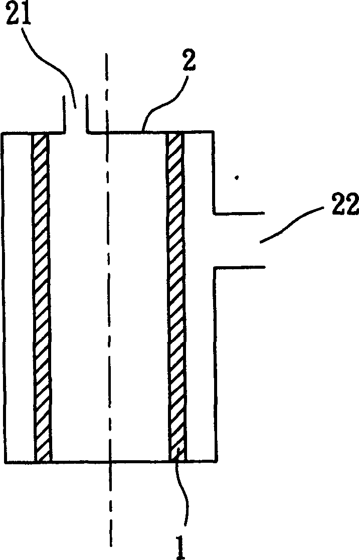
[0004] Obviously, the effective area of ​​the known filtering device is much larger than the cross-sectional area of ​​the fluid inlet because of the effective area of ​​the filter screen, so the flow velocity of the fluid flowing through the filter screen is much smaller than the flow rate of the fluid in the inlet pipeline, and the fluid in the filter screen is only perpendicular to the filter screen. The speed of the surface of the mesh, so there is no obvious liquid flow phenomenon in the filter device, resulting in the impurities or sediments in the filter device of the prior art are easy to deposit on the filter screen to form a filter cake, and when there are impurities deposited on the filter screen, it will gradually decrease The effective area of ​​the filter screen, when the effective area of ​​the filter screen is reduced to less than the cross-sectional area of ​​the inlet pipeline, the pressure difference (ΔP) between the filter inlet 21 and the outlet 22 will rise rapidly. In order to protect the normal operation of the instrument, the industry will Set the limit of the pressure difference according to the actual demand. When the pressure difference reaches the set value, it must be shut down to clean the filter in the filter device, so that the device cannot be operated continuously, causing great inconvenience and distress to the user, and some In order to avoid the above-mentioned downtime situation, the operators must install an additional set of filter devices, and use switching methods to perform cleaning and maintenance work, which will inevitably increase the cost of the entire filter device.
[0005] read on figure 2 , which is a schematic diagram of the relationship between the operating time of the filter device and the pressure difference. When the filter device is first used, there must be a certain pressure difference, but the pressure difference must be within the allowable design range. However, as time goes by When the extension and the continuous accumulation of impurities and sediments in the liquid on the filter screen will cause the pressure difference to increase continuously and exceed the original set value (such as figure 2 a) must be shut down for maintenance work

Method used


Image

  • Cross-flow filter function possessed filter device and operation method
  • Cross-flow filter function possessed filter device and operation method
  • Cross-flow filter function possessed filter device and operation method

Examples


Embodiment Construction

[0035] The present invention will be described in detail below with specific examples in conjunction with the accompanying drawings, so as to have a deeper understanding of the present invention.

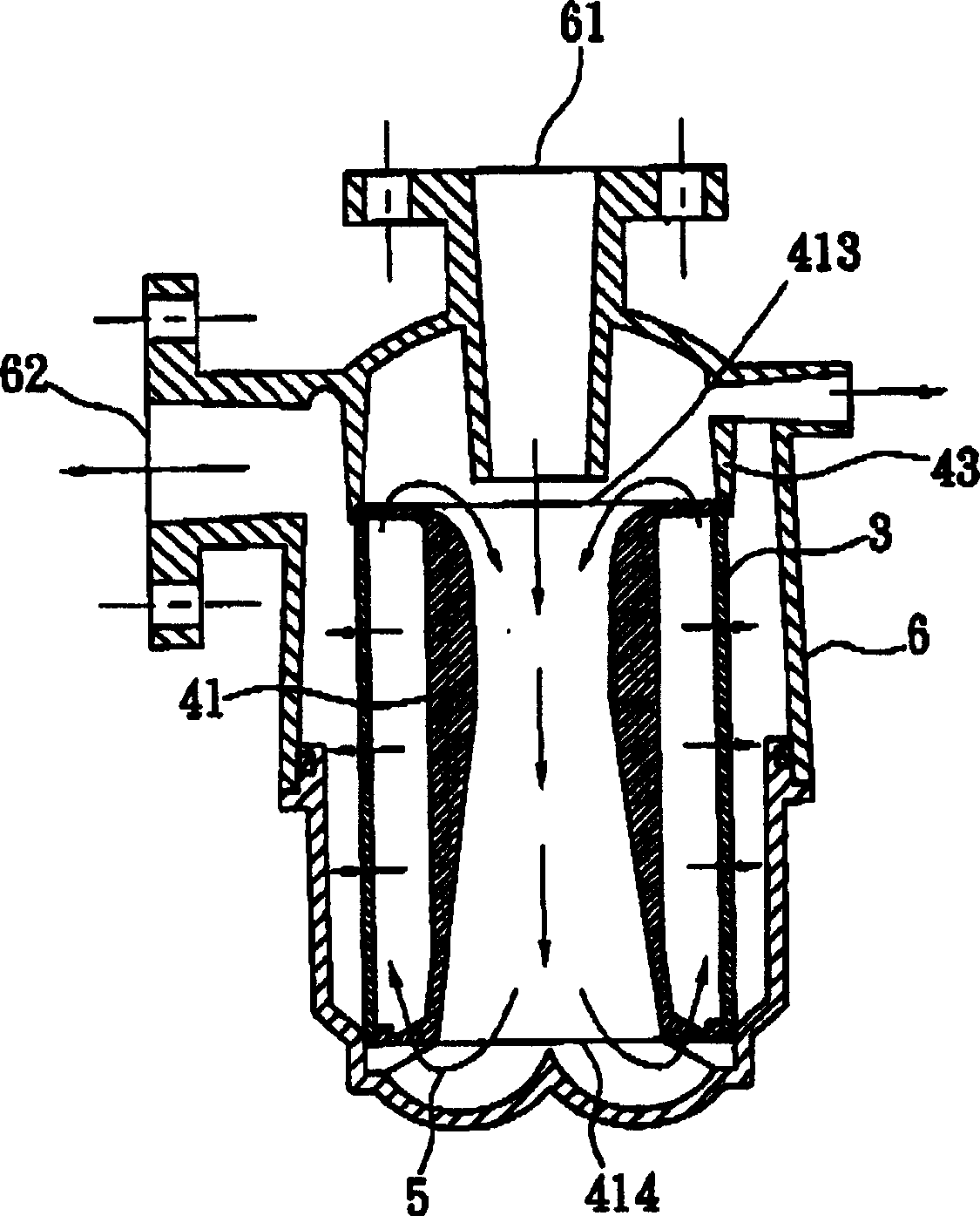
[0036] The present invention proposes a filter device with cross-flow function, especially a filter device capable of generating cross-flow so that filter cakes are not easily produced on the filter. Its structure is simple, and it can increase the effective operating time of the filtering device, and can operate continuously without stopping.

[0037] According to Darcy's Law: J≡(1 / A)(dV / dT)={Δp / [η*(Rm+Rc)]}

[0038] J: filtrate flux (permeate flux)

[0039] A: effective surface area of ​​filter media

[0040] V: total volume of filtrate (total volume of permeate)

[0041] T: Filtration time

[0042] Δp: Pressure drop imposed across the cake and filter media

[0043] η: filtrate viscosity (viscosity of the permeate)

[0044] Rm: resistance of the filter media

[0045] Rc: re...


PUM


Abstract

A method for prolonging operation time and improving filtering efficiency of a filter by generating cross flow is disclosed. The filtering device with cross flow function comprises : a filtering screen; a casing for containing the filtering screen; in which there is a fluid entrance and a fluid outlet; a diffuser on screen vertical direction; and a waste liquid discharging opening for discharging waste liquid with high concentration of impurity.

Description

technical field [0001] The present invention relates to a filtering device with cross-flow filtering function and its usage method, especially to a filtering device which utilizes cross-flow to prevent cake from being formed on the filter. Background technique [0002] With the continuous advancement of science and technology, many instruments have different requirements for the liquid used in the operation process to maintain the normal service life of the instrument. Therefore, the industry will install a filter device in the front of the liquid supply pipe. The filter device first filters the impurities or sediments in the liquid, and then provides the filtered liquid to the instrument for use. On the other hand, with the gradual emphasis on the concept of green environmental protection, the government has increasingly strict requirements on the quality of industrial discharge water, so the application of filter devices is becoming more and more common. [0003] Currentl...

Claims


Application Information

Patent Timeline
IPC IPC(8): B01D29/35
Inventor 张世昌
Owner 张世昌
Learn More