
Low power consumption permanent magnet biased axial magnetic bearing

A technology of axial magnetic bearing and permanent magnet bias, applied in the direction of shafts and bearings, bearings, bearing components, etc., can solve the problems of large reluctance, large excitation current, and large power consumption of permanent magnets, and achieve reduced copper consumption, Reduce the effect of controlling the power amplifier loss and low iron loss

Inactive Publication Date: 2006-08-16
BEIHANG UNIV
View PDF0 Cites 2 Cited by
  • Summary
  • Abstract
  • Description
  • Claims
  • Application Information

AI Technical Summary

Problems solved by technology

[0002] The key to the low power consumption of permanent magnet electromagnetic bearings is to ensure that the magnetic flux generated by the excitation coil does not pass through the permanent magnets. However, some of the existing permanent magnet bias axial magnetic bearing structures are based on ordinary axial electromagnetic bearings. A permanent magnet is placed on the electromagnetic magnetic circuit so that the magnetic flux generated by the control coil passes through the permanent magnet. Since the permanent magnet has a large reluctance, a large excitation current is required for the control coil to generate a certain electromagnetic flux. In addition, some structures Although the electric excitation magnetic circuit does not pass through the permanent magnet, it passes through the rotor laminated core vertically, which requires a large electric excitation magnetic potential to meet the control requirements, so the existing permanent magnet bias axial magnetic bearing has work Disadvantages of high consumption, large volume and heavy weight

Method used


Image

  • Low power consumption permanent magnet biased axial magnetic bearing
  • Low power consumption permanent magnet biased axial magnetic bearing
  • Low power consumption permanent magnet biased axial magnetic bearing

Examples


Embodiment Construction

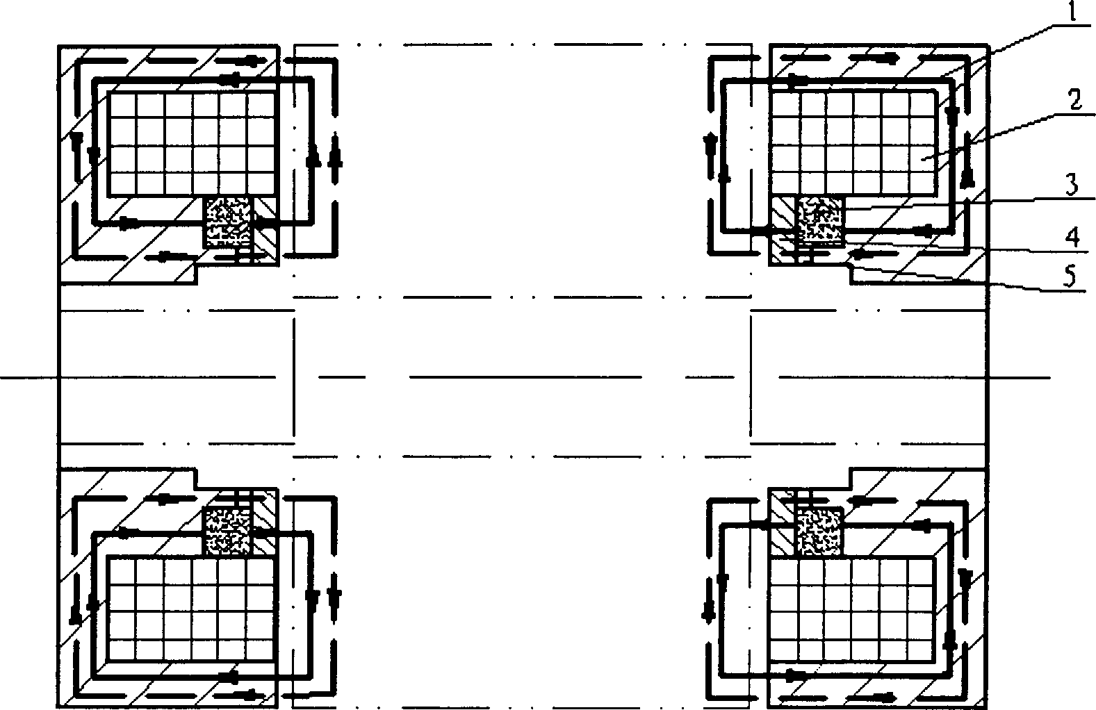
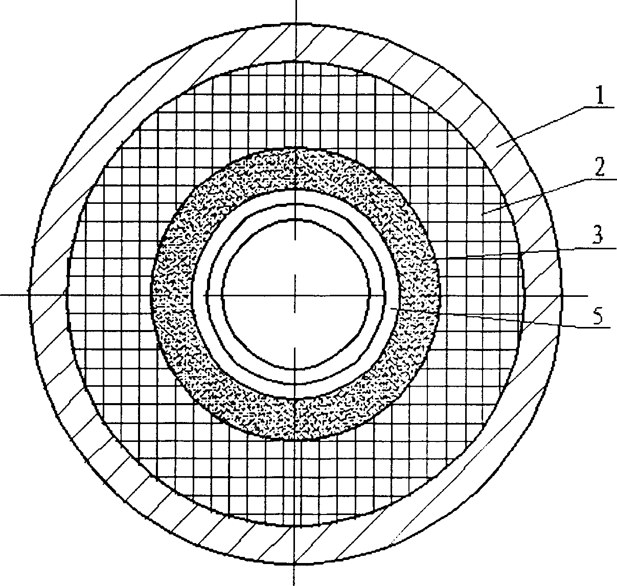
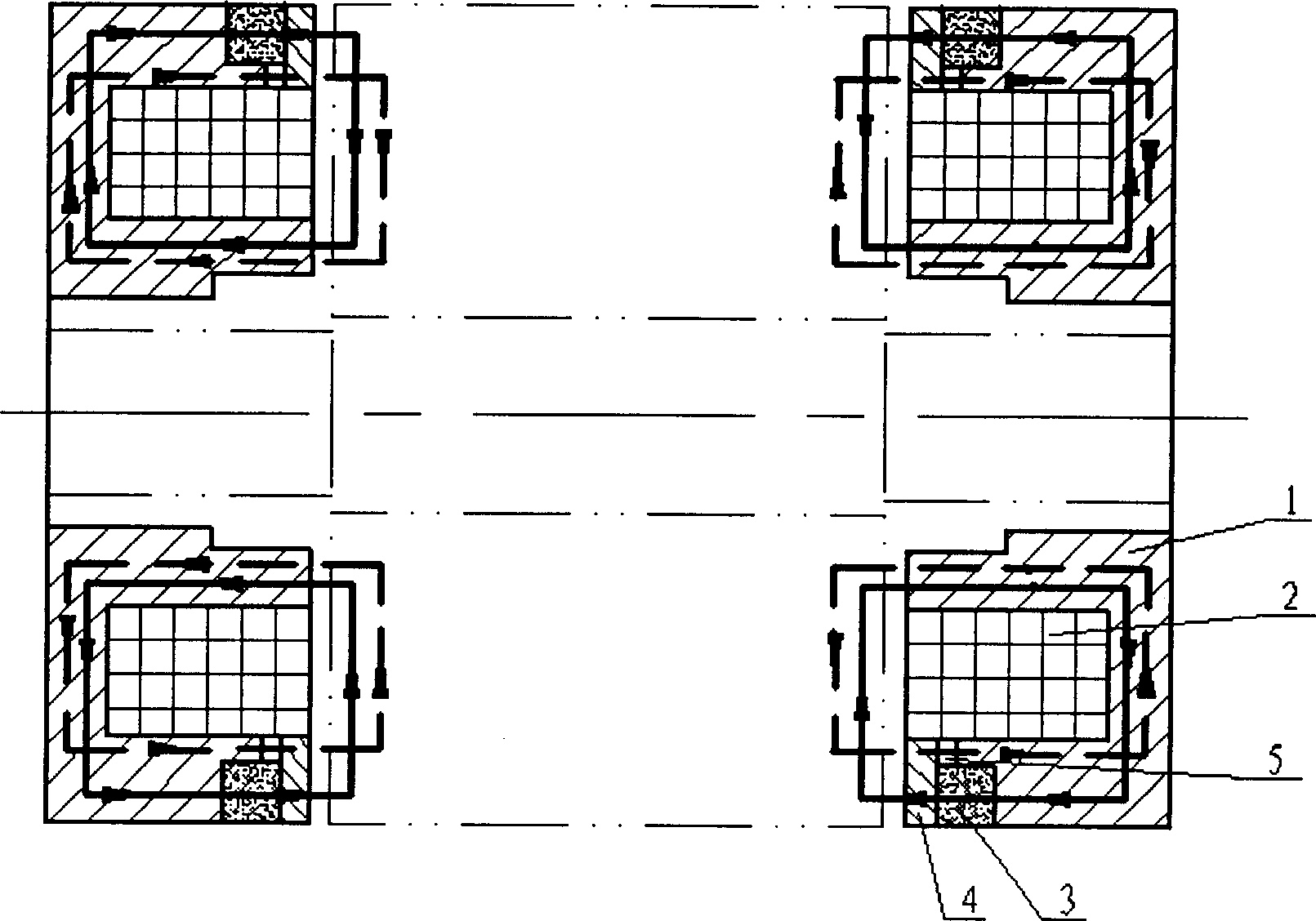
[0013] Such as figure 1 , 2 As shown, it is the low-power permanent magnet bias axial magnetic bearing with inner magnetic steel and outer excitation coil of the present invention, which is the basic form of the present invention. It consists of bearing body 1, excitation coil 2, permanent magnet 3, and magnetic conduction ring 4. Composed of 5 excitation air gaps. The permanent magnet 3 is closely attached to the bearing body 1, and generates magnetic fields of different polarities on the inner and outer air gaps of the magnetic bearing. The excitation coil 2 is wound on the bearing body 1 to generate an excitation magnetic flux. The magnetic conduction ring 4 is closely attached to the On the permanent magnet 3, an excitation air gap 5 is formed between the magnetic conduction ring 4 and the bearing body 1, and the excitation air gap provides a magnetic circuit for the magnetic flux generated by the excitation coil.

[0014] Such as figure 1 , 2 As shown, assuming that t...


PUM


Abstract

An axial magnetic bearing consists of a bearing body, an exciting coil, a permanent magnet, a magnetizer ring and an exciting gap. The permanent magnet contacting closely to the bearing body produces magnetic fields in different polarities separately in the inner and outer gaps; the exciting coil wound onto the bearing body generates the exciting magnetic flux; and the magnetizer ring contacting closely to the permanent magnet forms exciting gap between the magnetizer ring and the bearing body for providing the magnetic flux the exciting coil generates with magnetic path. The axial magnetic bearings of the present invention are used in pair in machine and the corresponding parts are made of magnetic permeable material. The present invention has the advantages of low magnetic reluctance, low exciting cut, low power consumption, small size, light weight, easy manufacture, etc. and may be used as the no-contact support for rotating part in machine.

Description

Technical field [0001] The invention relates to a non-contact magnetic suspension bearing, in particular to a low-power permanent magnet bias axial magnetic bearing, which can be used as a non-contact support for rotating parts in mechanical equipment such as motors and machine tools. Background technique [0002] The key to the low power consumption of permanent magnet electromagnetic bearings is to ensure that the magnetic flux generated by the excitation coil does not pass through the permanent magnets. However, some of the existing permanent magnet bias axial magnetic bearing structures are based on ordinary axial electromagnetic bearings. A permanent magnet is placed on the electromagnetic magnetic circuit so that the magnetic flux generated by the control coil passes through the permanent magnet. Since the permanent magnet has a large reluctance, a large excitation current is required for the control coil to generate a certain electromagnetic flux. In addition, some str...

Claims


Application Information

Patent Timeline
Patent Type & Authority Patents(China)
IPC IPC(8): F16C32/04F16C39/06H02K7/09
Inventor 房建成徐衍亮马善振孙津济
Owner BEIHANG UNIV
Learn More