Rotor spinning machine

A rotor spinning machine and spinning unit technology, applied in spinning machines, open-end spinning machines, continuous winding spinning machines, etc., can solve problems such as poor joint quality, and achieve improved joint quality and precision The effect of request reduction

Inactive Publication Date: 2006-08-30
RIETER CZ AS
View PDF1 Cites 2 Cited by
  • Summary
  • Abstract
  • Description
  • Claims
  • Application Information

AI Technical Summary

Problems solved by technology

[0006] The disadvantage of this solution is that there are high demands on the precision of the stopping of the guarding device in front of the operating unit of the rotor spinning machine and equally high demands on the precision of the construction and adjustment of the movement path of the compressed air supply, which Both requirements are necessary so that the end can always be seated exactly on the check valve of the operating unit to be attended
Failure to do this and the splicing operation will either fail or result in poor piecing quality necessitating repeated splicing

Method used


Image

  • Rotor spinning machine
  • Rotor spinning machine
  • Rotor spinning machine

Examples


Embodiment Construction

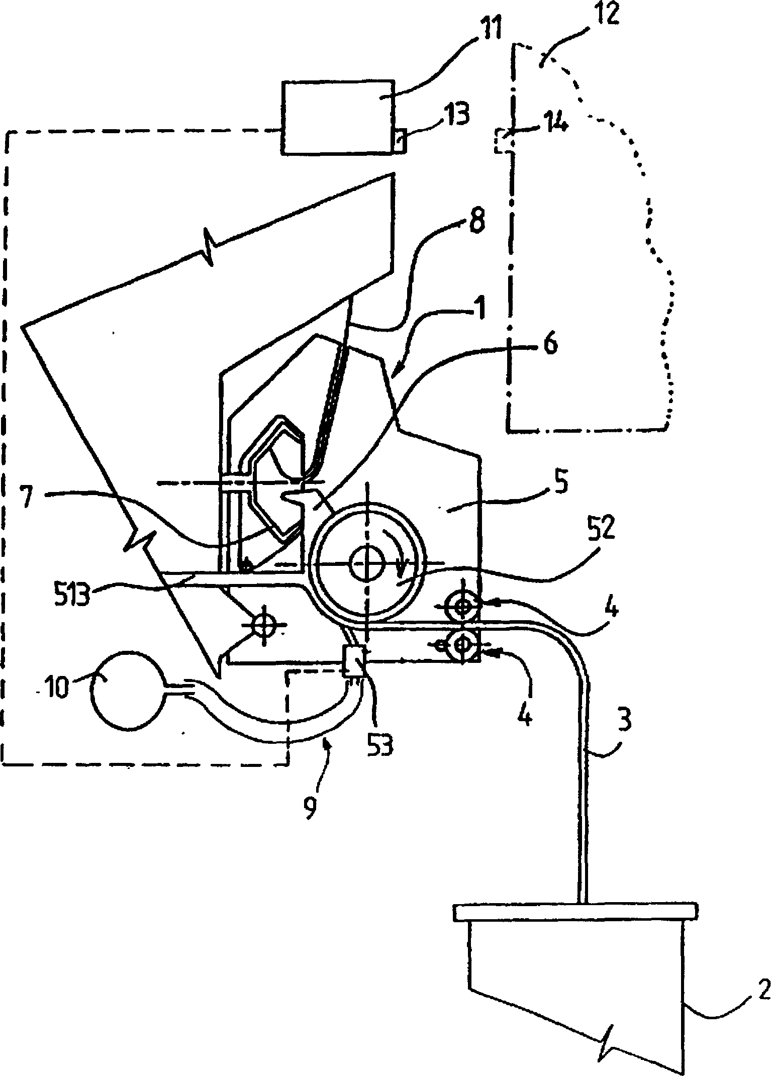
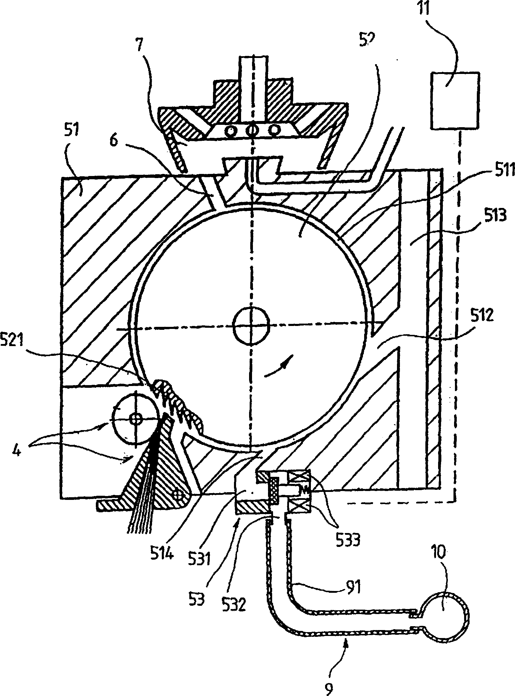
[0017] A rotor spinning machine has several operating units arranged side by side. Each operating unit produces yarn from a sliver of textile fibers and winds it up on bobbins.

[0018] Rotor spinning machines are made fully automatic or semi-automatic; the invention cannot be used on spinning machines controlled only by humans.

[0019] The fully automatic rotor spinning machine is equipped with a supervisory device which can be adjusted along the operating unit of the rotor spinning machine and in the operating unit when spinning is to be restarted and / or when a full bobbin is replaced with an empty tube. A device for monitoring operations.

[0020] The semi-automatic rotor spinning machine is partly supervised manually, and partly equipped with an automatic device for yarn splicing. Associated with each operating unit of a semi-automatic rotor spinning machine is a control unit whose purpose is to control and / or collect data, for which purpose it is connected to the slive...


PUM


Abstract

The invention relates to a rotor spinning machine comprising a plurality of operating units situated next to each other, each of which contains a spinning unit (1) with a singling-out device (5) having in its body a rotatably mounted combing roller (52) equipped on its circumferential surface with an operative coating (521) around which there is provided in the body of the singling-out device a circumferential fibre channel (511) whose operative section extends in the sense of rotation of the combing roller (52) from the mouth of the sliver feeding device (4) to the supply channel (6) bringing the singled-out fibres into the rotor, said circumferential fibre channel (511) having provided therein the mouth of a closable auxiliary supply channel (514) for pressure air. The closable auxiliary supply channel (514) of pressure air of each spinning unit (1) is connected to the outlet (531) of a closable means (53) related thereto whose inlet (532) is by a pressure air pipe (9) connected to a pressure air source (10).

Description

technical field [0001] The invention relates to a rotor spinning machine with a plurality of operating units arranged side by side, each operating unit comprising a spinning unit with a carding device in which a rotatably mounted The open carding roller is provided with a working cover on its outer peripheral surface, and a fiber channel along the circumference is provided around the working cover in the carding device, and its working part extends along the rotation direction of the carding roller, from The sliver feeder mouth extends to the supply duct to bring the separated filaments into the rotor, and the working part of the circumferential fiber channel is provided in it with a closable opening of the pressurized air auxiliary supply duct. Background technique [0002] In the rotor spinning machine, when each yarn on each spinning unit is interrupted, whether it is due to yarn breakage or because the bobbin is full and needs to be replaced, spinning must be restarted, ...

Claims


Application Information

Patent Timeline
IPC IPC(8): D01H4/08D01H4/24D01H4/32D01H4/36D01H4/22D01H4/30D01H4/34D01H4/44D01H4/50
CPCD01H4/32D01H4/44D01H4/22
Inventor J·鲁德维策克P·考撒利克J·马克尔T·特萨
Owner RIETER CZ AS
Why Eureka
Try Eureka