Fuel injection pump

A technology of fuel injection pump and fuel inlet, which is applied in the direction of fuel injection pump, fuel injection device, fuel injection control, etc., can solve heating and other problems, and achieve the effect of improvement, small pressure loss, and small flow resistance

Inactive Publication Date: 2006-09-06
ROBERT BOSCH GMBH
View PDF1 Cites 0 Cited by
  • Summary
  • Abstract
  • Description
  • Claims
  • Application Information

AI Technical Summary

Problems solved by technology

It has been proven in practice that heating of the electrical components in the control housing causes problems

Method used


Image

  • Fuel injection pump
  • Fuel injection pump
  • Fuel injection pump

Examples


Embodiment Construction

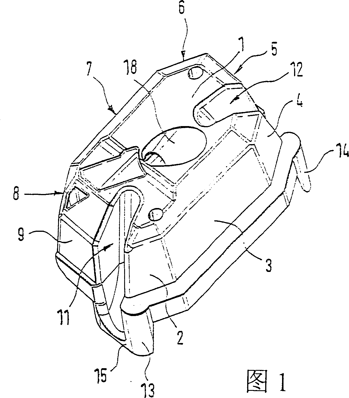
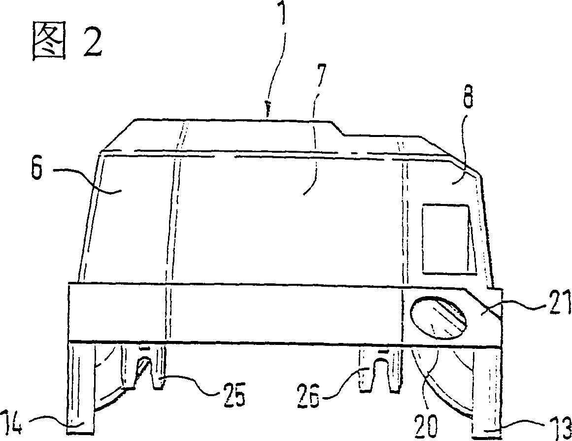
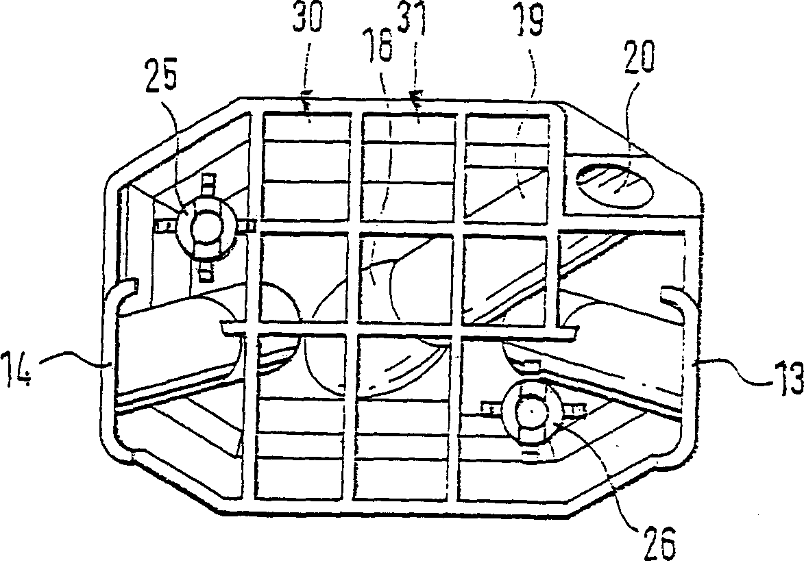
[0018] The filler piece shown in perspective in FIG. 1 is accommodated in a cavity formed between the top side of the pump housing and the bottom side of the control unit housing of a jet pump according to the invention. A fuel inlet opens into the cavity, through which fuel reaches the cavity from a fuel tank. The fuel can either be delivered into the cavity by means of a backing pump, or it can be sucked in only by the delivery pump of the jet pump. A connecting line leads from the cavity to the delivery means of the jet pump. The opening for the connecting duct is arranged in the cavity above the opening for the fuel inlet. This achieves that the cavity is always filled with fuel up to a certain level. Inevitably in operation, there will also be a certain amount of air in the cavity. The lower part of this cavity is bounded by the pump housing of the jet pump. However, the upper part of the cavity is bounded by the bottom of the control unit housing. The control unit h...


PUM


Abstract

The present invention relates to a fuel injection pump for internal combustion engines, having a pump housing, in which a feed device is accommodated, whose operation is controlled with the aid of a control unit that is accommodated in a control-unit housing mounted to the pump housing. In order to ensure that the control-unit housing is sufficiently cooled, a cavity, into which a fuel inlet empties and at which a connecting line leading to the feed device originates, is formed between the upper side of the pump housing and the lower side of the control-unit housing; a filler piece having an inlet tulip (18) being situated in the cavity, the delivered fuel being directed from the cavity, through the inlet tulip and the connecting line, to the feed device.

Description

technical field [0001] The invention relates to a fuel injection pump for an internal combustion engine, which has a pump housing in which a delivery device is installed, the operation of which is controlled by means of a control device which is installed in a control device housing , the control housing is assembled on the pump housing. Background technique [0002] A jet pump of this type is known from DE-OS3403073A1. In the known injection pump, the fuel to be delivered is led through the control unit housing for cooling. In practice, it has been found that the heating of electrical components in the housing of the control unit can cause problems. Contents of the invention [0003] The object of the invention is to ensure that the control housing is sufficiently cooled without the electrical components located in the control housing being flushed with fuel. [0004] According to the invention, a fuel injection pump for an internal combustion engine is proposed, which...

Claims


Application Information

Patent Timeline
IPC IPC(8): F02M53/00F02M55/00F02M59/44F02M63/00F02D41/30
CPCF02M53/00F01P2050/30F02D41/3005F02M55/00F02M59/44F02M63/00
Inventor 维尔纳·菲舍尔约尔格-彼德·菲舍尔
Owner ROBERT BOSCH GMBH
Why Eureka
Try Eureka