
Photoelectric type semiconductor safety unit

A security unit and semiconductor technology, applied in electrical components, circuit devices, emergency protection circuit devices for limiting overcurrent/overvoltage, etc., can solve problems such as chronic air leakage, slow alarm speed, and endangering equipment and personal safety. Achieve the effects of improving response speed, increasing functions, and saving maintenance costs

Inactive Publication Date: 2006-10-18
卫其昌
View PDF0 Cites 0 Cited by
  • Summary
  • Abstract
  • Description
  • Claims
  • Application Information

AI Technical Summary

Problems solved by technology

[0003] The common problem of this kind of security unit is: because the gas discharge tube inevitably has different degrees of chronic air leakage, so the service life is short, generally 2 to 3 years, it needs to be replaced regularly, and once it fails, it will endanger equipment and personal safety; Because the melting of low-temperature tin blocks takes a certain amount of time, at 2.5 amps, it takes about 5 to 15 seconds, so the alarm speed is relatively slow; because there is a fusible wire connected in series in the communication circuit of the security unit, its rated value is general It is about 2.5 amps. When the current passing through exceeds 2.5 amps, it will generally fuse within 2 seconds.
This simple replacement method only solves the short life problem caused by the use of gas discharge tubes in the security unit, and does not give full play to the advantages of semiconductor tubes.

Method used


Image

  • Photoelectric type semiconductor safety unit
  • Photoelectric type semiconductor safety unit
  • Photoelectric type semiconductor safety unit

Examples


Embodiment Construction

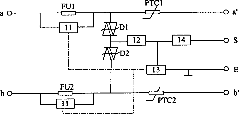
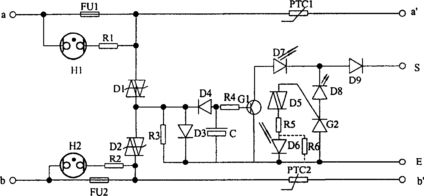
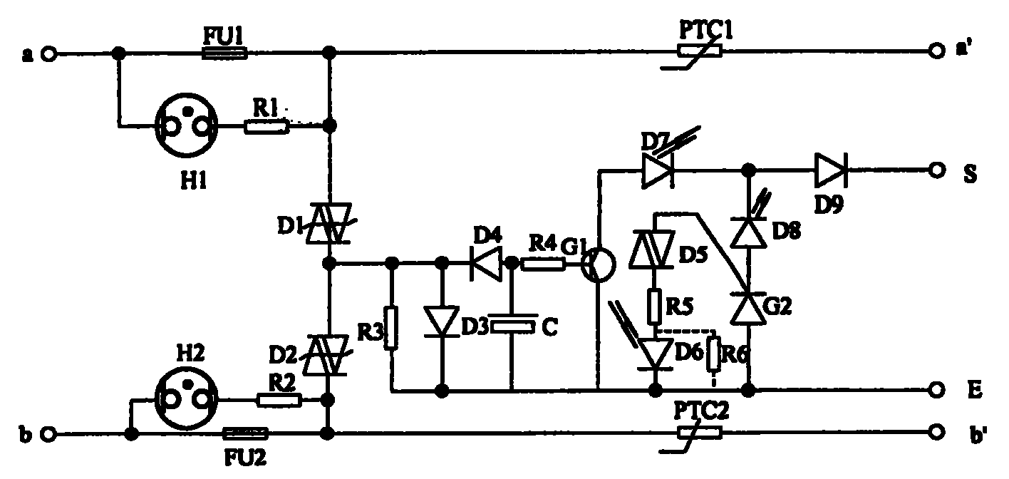
[0019] see figure 1 , The photoelectric semiconductor security unit is connected between the incoming terminals a, b of the telephone cable, the incoming terminals a', b' of the telecommunication switching equipment and the terminals S, E of the alarm system, mainly including two parts of the protective device and the alarm circuit. The protective device includes fuses FU1 and FU2 respectively connected in series in a, a' and b, b' lines, positive temperature coefficient thermistors PTC1 and PTC2, and two series-connected semiconductor tubes connected in parallel on lines a and b. D1, D2, when there is overvoltage at terminal a or overvoltage at terminal b or overvoltage at both terminals a and b, and the current exceeds the rated value of the fuse, fuse FU1 will blow or FU2 will blow or FU1 and FU2 will blow at the same time; When the current does not exceed the rated value of the fuse, the semiconductor tube D1 or D2 is broken down, and the overvoltage is "short-circuited" t...


PUM


Abstract

The invention relates to a photoelectric semiconductor security unit, which is connected between the telephone cable incoming line and the alarm system of the telecommunication switching equipment, and is used to solve the problems of large and small current alarms and the like. Including protection device and alarm circuit two parts. Protection devices include fuses, thermistors and semiconductor tubes for overvoltage protection of communication equipment; alarm circuits include large current sampling circuits, small current sampling amplifier circuits, large current alarm photoelectric trigger memory circuits, and large and small current alarm indication circuits. Two series-connected semiconductor tubes are connected to the output terminal of the fuse in parallel; the large current sampling circuit is connected in parallel to both ends of the fast fuse; the input terminal of the small current sampling amplifier circuit is connected to the serial connection point of the semiconductor tube, and the output terminal is connected to Alarm system; the output end of the high current alarm photoelectric trigger memory circuit is connected to the alarm system. The light-emitting device and the light-receiving device of the high-current sampling circuit are used to trigger the work of the high-current alarm photoelectric trigger memory circuit.

Description

technical field [0001] The present invention relates to a security technology for communication equipment, more specifically to a semiconductor security unit, which is applied to the main distribution frame of a telephone exchange and connected between the incoming cable and the telephone exchange equipment. Provide protection and alarm for overvoltage, overcurrent protection and lightning strike protection. Background technique [0002] The security unit is a protective device for overvoltage and overcurrent in telecommunications equipment such as distribution frames. Most of the security units currently in use use gas discharge tubes for overvoltage and overcurrent protection components. In addition to the gas discharge tube, the security unit using the gas discharge tube also includes a compression spring, a metal jacket of the discharge tube, a short circuit, a low-temperature tin block (or a hot coil), a propulsion shaft, an alarm signal moving piece, and an alarm sign...

Claims


Application Information

Patent Timeline
Patent Type & Authority Patents(China)
IPC IPC(8): H02H9/02H02H9/04H02H9/06
Inventor 卫其昌
Owner 卫其昌
Learn More