Auto-collimation interference measurement system for three dimensional angular distortion of object

An interferometric measurement and self-collimation technology, which is applied to measurement devices, instruments, optical devices, etc., can solve the problem that the background technology cannot measure three-dimensional angular deformation, and achieve the effects of improved accuracy, easy implementation, and simple optical system structure.

Inactive Publication Date: 2007-01-17
CHANGCHUN INST OF OPTICS FINE MECHANICS & PHYSICS CHINESE ACAD OF SCI
View PDF4 Cites 0 Cited by
  • Summary
  • Abstract
  • Description
  • Claims
  • Application Information

AI Technical Summary

Problems solved by technology

[0005] In order to solve the problem that the background technology cannot measure three-dimensional angular deformation, the purpose of the present invention is to provide a self-collimation interferometry system capable of measuring three-dimensional angular deformation

Method used


Image

  • Auto-collimation interference measurement system for three dimensional angular distortion of object
  • Auto-collimation interference measurement system for three dimensional angular distortion of object

Examples


Embodiment Construction

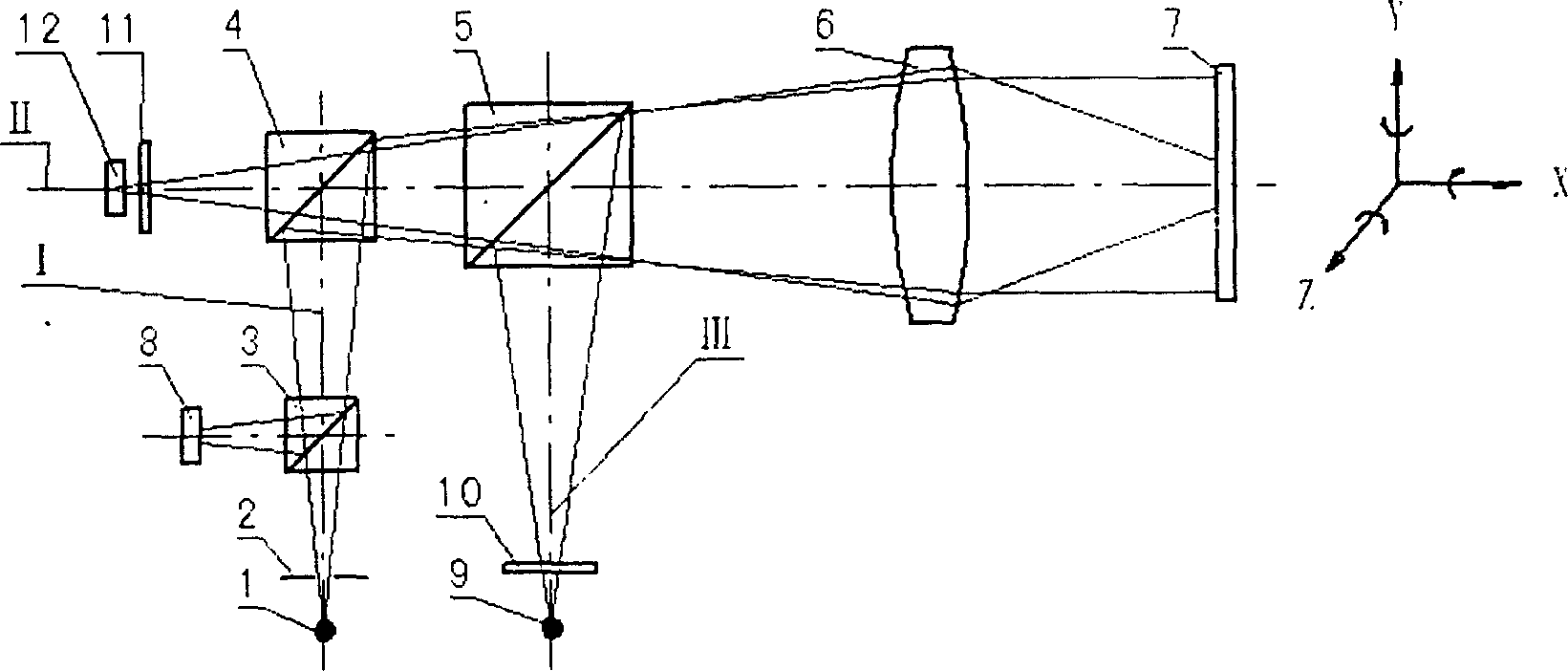
[0013] The invention presses figure 2 The schematic diagram shown is implemented. The first light source 1, the diaphragm 2, the first dichroic prism 3, the second dichroic prism 4, the third dichroic prism 5, the objective lens group 6, the reflecting mirror 7, and the first CCD detector 8 form a main optical path; The light source 9, the autocollimating grating 10, the third beam splitting prism 5, the objective lens group 6, the reflecting mirror 7, the second beam splitting prism 4, the aiming grating 11 and the second CCD detector 12 form another main optical path; the second beam splitting prism 4, The third dichroic prism 5, the objective lens group 6, and the grating mirror 7 are the common optical path part of the two main optical paths.

[0014] The first light source 1 can be an infrared light source; the diaphragm 2 can be a small aperture diaphragm; the first dichroic prism 3, the second dichroic prism 4, the third dichroic prism 5, and the reflecting mirror 7 can be ...


PUM


Abstract

This invention belongs to photoelectricity measuring technique field and relates to a self-collimation intervention measuring system which comprises 1 Number one light source, 2 diaphragm, 3 Number one beam splitter, 4 Second beam splitter, 5 Third beam splitter, 6 object lens group, 7 reflectoscope, 8 CCD detector, 9 Second light source, 10 self-collimation grating, 11 aiming grating, 12 CCD detector. The invention provides a new method for measuring the three-dimensional deformation of an object based on the principle of self-collimation intervention and solves the problem that background technique can't measure the three-dimensional deformation of an object. There are two main light paths in the self-collimation intervention system of this invention and one is self-collimation light path which can measure the two-dimensional deformation of an object and the other is grating invention light path which can measure one-dimensional deformation of a object. And the accuracy of the deformation measured is improved with the increase of the grating frequency by the use of grating invention.

Description

Technical field [0001] The invention belongs to the field of photoelectric measurement technology, and relates to a self-collimating interferometric measurement system. Background technique [0002] The self-collimation method can measure the small-angle deformation of an object, but it is commonly used to measure one-dimensional or two-dimensional angular deformation, and the self-collimation method can only measure two-dimensional angular deformation at most. [0003] The existing technology closest to the present invention is the mature photoelectric auto-collimation measurement system, the principle of which is as follows figure 1 As shown, it is composed of a light source 1, a diaphragm 2, a beam splitting prism 3, an objective lens group 4, a reflecting mirror 5 and a detector 6. [0004] This photoelectric self-collimation measurement system can only measure the one-dimensional angular deformation of the object or the two-dimensional angular deformation of the object, but...

Claims


Application Information

Patent Timeline
Patent Type & Authority Patents(China)
IPC IPC(8): G01B11/26
Inventor 乔彦峰李向荣李清安郭平平张尧禹
Owner CHANGCHUN INST OF OPTICS FINE MECHANICS & PHYSICS CHINESE ACAD OF SCI
Why Eureka
Try Eureka