Objective lens, optical pickup device and information recording regeneration method
An optical pickup and information recording technology, applied in the field of objective lens system, can solve the problems of deteriorating focus noise, increasing noise signal during focusing process, increasing spot light, etc.
- Summary
- Abstract
- Description
- Claims
- Application Information
AI Technical Summary
Problems solved by technology
Method used
Image

Examples
Embodiment 1
[0159] This embodiment is related to the above-mentioned first embodiment, and it is about using DVD as the first optical information recording medium with high recording density and using CD as the second optical information recording medium with low recording density, and it is possible to store information on them respectively. Examples of recording or reproducing objective lenses.
[0160] In DVD, the thickness of the transparent substrate of the optical information recording medium is 0.6mm, the necessary numerical aperture NA1=0.60, and the wavelength of the light source λ 1 =655nm, in CD, the thickness of the transparent substrate of the optical information recording medium is 1.2mm, the necessary numerical aperture NA2=0.45, the light source wavelength λ 2 =785nm.
[0161] Both surfaces of the objective lens are aspheric surfaces represented by [Formula 1]. Here, Z is the axis in the direction of the optical axis, h is the axis perpendicular to the optical axis, r is...
Embodiment 2
[0214] This embodiment is related to the above-mentioned second embodiment, and it is about using a DVD as a first optical information recording medium with a high recording density and using a CD as a second optical information recording medium with a low recording density, and it is possible to store information on them separately. Examples of recording or reproducing objective lenses. Here, descriptions that overlap with Embodiment 1 are omitted.
[0215] In this embodiment, the feature is that by setting the manufacturing wavelength (the wavelength used for the shape design of the diffractive structure) to a shorter wavelength than the DVD wavelength in the diffractive structure of the outer optical function region, it is possible to ease the passage of time when using a CD. Noise caused by beams in the outer area.
[0216] [Table 3] provides the lens data of the objective lens of the present embodiment, and the spherical aberration diagram is shown in Figure 9 . Figu...
Embodiment 3
[0261] This embodiment is related to the above-mentioned third embodiment, and it is about using DVD as the first optical information recording medium with high recording density and using CD as the second optical information recording medium with low recording density, and it is possible to store information on them respectively. Examples of recording or reproducing objective lenses.
[0262] In DVD, the thickness of the transparent substrate of the optical information recording medium is 0.6mm, the necessary numerical aperture NA1=0.60, and the wavelength of the light source λ 1 =655nm, in CD, the thickness of the transparent substrate of the optical information recording medium is 1.2mm, the necessary numerical aperture NA2=0.45, the light source wavelength λ 2 =785nm.
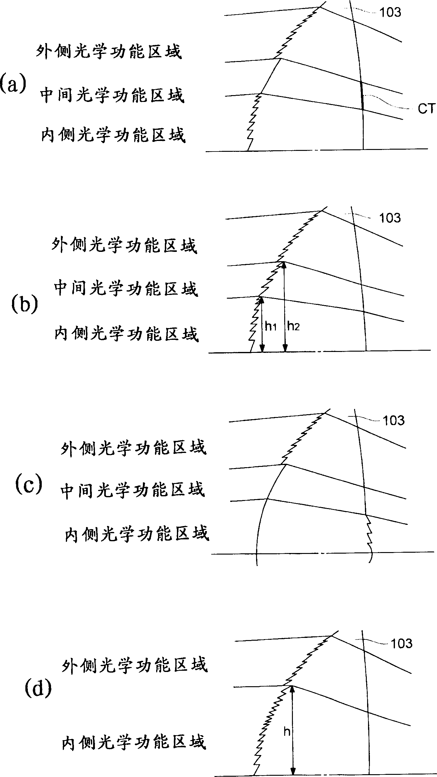
[0263] The objective lens has two aspherical surfaces, and the surface on the light source side is composed of three optical functional areas, which are used for different purposes. Such as figure 2 As ...
PUM
| Property | Measurement | Unit |
|---|---|---|
| Thickness | aaaaa | aaaaa |
| Thickness | aaaaa | aaaaa |
Abstract
Description
Claims
Application Information
PatSnap Eureka turns technology decisions into work you can execute. Powered by our Innovation Knowledge Graph, it runs expert workflows across engineering, life sciences, materials and intellectual property. Get your review-ready output in minutes.


