
Induction motor

A technology for induction motors and motor brackets, applied to asynchronous induction motors, synchronous motors for single-phase current, electrical components, etc., can solve problems such as difficulty in fixing the rotor, wasting magnetomotive force, and rising costs

Inactive Publication Date: 2007-01-31
FUJITSU GENERAL LTD
View PDF8 Cites 4 Cited by
  • Summary
  • Abstract
  • Description
  • Claims
  • Application Information

AI Technical Summary

Problems solved by technology

[0006] However, in the conventional induction motor having the above configuration, since the stator and the rotor are composed of coils of electromagnetic steel sheets, it is difficult to fix the stator to the frame (casing), and it is also difficult to fix the rotor to the rotating shaft. question
[0007] This problem can be solved by integrally forming the bracket with resin molding on the outer peripheral side of the stator, but the use of resin will increase the cost, and there is a problem in disposal, so it is desirable to avoid it from the perspective of environmental protection.
[0008] Also, from the perspective of the stator core and the rotor core, since there are open slots, and the opening of the slots is enlarged to facilitate the insertion of coils, the reluctance of the air gap tends to increase, which wastes the magnetomotive force and causes a decrease in efficiency.
Not only that, the spatial variation of the magnetic flux density on the air gap is also increased, and thus vibration or noise is generated
[0009] In order to eliminate this, the slot opening of the stator core can also be reduced, but in that case, not only a dedicated winding machine is required, but also another problem that the efficiency of the winding operation is reduced
Likewise, if the slot opening of the rotor core is also reduced, its rotor coils are difficult to insert into the slots
[0010] In addition, as an alternative method of forming the rotor coil on its narrow slot opening, die casting can also be considered, but there are disadvantages such as increased cost due to increased manufacturing processes, etc.

Method used


Image

  • Induction motor
  • Induction motor
  • Induction motor

Examples


Embodiment Construction

[0038] Hereinafter, several embodiments of the present invention will be described with reference to the drawings, but the present invention is not limited to these embodiments.

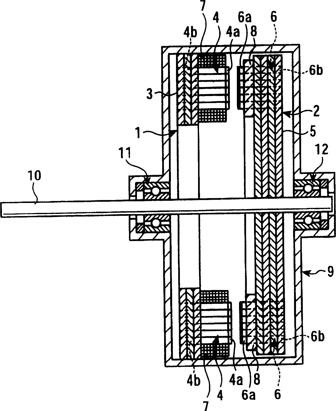
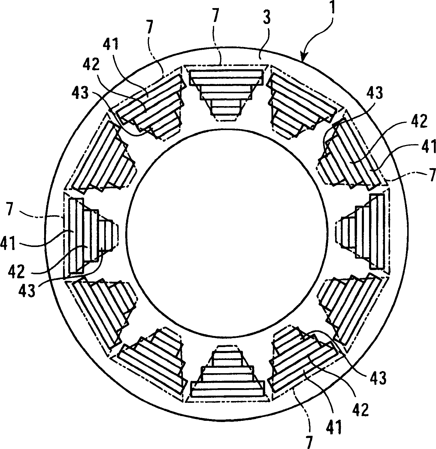
[0039] First, refer to Figure 1 to Figure 4 An induction motor according to a first embodiment of the present invention will be described. This induction motor is a flat type induction motor in which a stator 1 and a rotor 2 both formed in a disc shape are arranged coaxially with respect to a rotating shaft 10, and they face each other with an air gap in the axial direction.

[0040] The stator 1 has a stator back 3 and stator teeth 4 , and the rotor 2 also has a rotor back 5 and rotor teeth 6 .

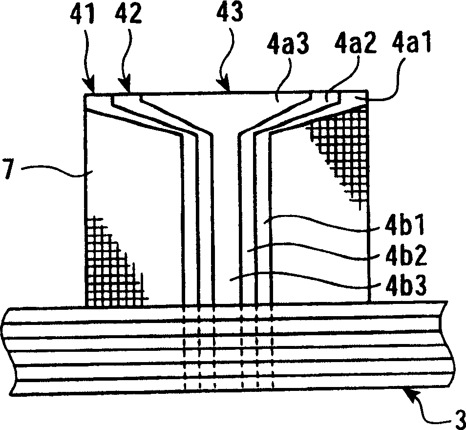
[0041]The stator tooth 4 has a tooth body (first tooth body) 4b, and a T-shaped tooth end portion (first tooth end portion) 4a (refer to image 3 ). The rotor tooth 6 also has a tooth main body (second tooth main body) 6b, and a T-shaped tooth end portion (second tooth main body) 6a for preventing coil ...


PUM


Abstract

In an axial-air-gap induction motor which has a disk-shaped stator and rotor placed coaxially around a rotating shaft with their surfaces opposing each other across a predetermined gap, the stator and rotor are each composed of a disk-shaped yoke and teeth fitted and secured in the yoke, making it easy to fasten the stator to the bracket, and the rotor to the rotating shaft, as well as to mount windings in the stator core and rotor core.

Description

technical field [0001] The present invention relates to an induction motor, if in more detail, it is a flat type (disc type) induction motor that will form a disc-shaped stator and a rotor coaxially arranged with an air gap in the axial direction, and particularly relates to an air conditioner Induction motors used. Background technique [0002] A flat induction motor is a motor in which a disc-shaped stator and a rotor are arranged coaxially with respect to the rotating shaft in a state where they face each other. Usually, the stator core and the rotor core have a strip-shaped electromagnetic steel sheet wound In the spiral wound body, a plurality of open grooves are formed at equal intervals in the circumferential direction from the outer circumference in the direction of the rotation axis and in the circumferential direction, leaving only a part of the electromagnetic steel sheet. [0003] The slot of the stator core is insulated, the main coil and the auxiliary coil are...

Claims


Application Information

Patent Timeline
Patent Type & Authority Patents(China)
IPC IPC(8): H02K1/12H02K1/22H02K1/02H02K17/02H02K19/02H02K1/08H02K1/18H02K1/24H02K16/00
CPCH02K16/00H02K17/02
Inventor 成田宪治藤冈琢志田边洋一伊藤彰浩芝本道宏N·吉罗贾特龙恩C·撒纳西蒂庞
Owner FUJITSU GENERAL LTD
Learn More