Anchoring method and end-bearing anchor

An anchoring method and anchor rod technology, applied in construction, sheet pile walls, foundation structure engineering, etc., to achieve the effects of reducing project costs, speeding up project progress, and reducing construction difficulty

Inactive Publication Date: 2007-02-07
张百全
View PDF5 Cites 0 Cited by
  • Summary
  • Abstract
  • Description
  • Claims
  • Application Information

AI Technical Summary

Problems solved by technology

[0003] The technical problem to be solved by this invention is how to increase the contact area between the anchor rod and the rock and soil, so that the anchor rod can not only be affected by the side resistance from the rock and soil, but also be affected by its end resistance, so as to increase the anchoring force and reduce the Anchor material consumption

Method used


Image

  • Anchoring method and end-bearing anchor
  • Anchoring method and end-bearing anchor
  • Anchoring method and end-bearing anchor

Examples


Embodiment 1

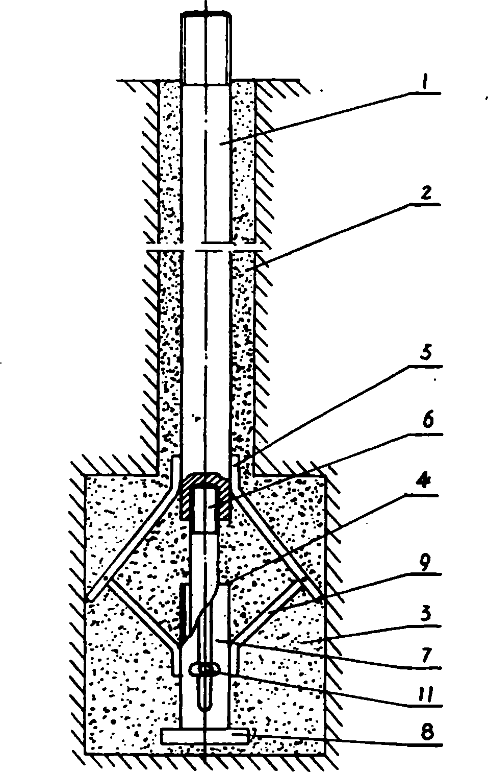
[0033] Such as figure 2 As shown, the present embodiment includes an anchor rod 1 arranged in an anchor hole 2, and is characterized in that an anchor head 4 is set under the anchor rod 1, which includes a sliding rod 7 and a stressed pull rod 5, and the stressed pull rod 5 can be used under external force Stretch under action, be located at the anchor rod 1 bottom, can set one or more than one, be directly welded on the anchor rod 1 or be fixed on the anchor rod 1 by bolt. Below the anchor rod 1, a sliding rod 7 is provided, which is placed in the anchor reaming hole 3 provided below the anchor hole 2. The sliding rod 7 is tubular, and its pipe wall is symmetrically provided with a long chute. The lower end of the upper sliding rod 6 is sleeved in the lower end of the lower sliding rod 7, and the pin rod 11 is fixed on the lower end of the upper sliding rod 6, and can pass through the chute of the lower sliding rod 7, driving the upper sliding rod 6 to move up and down in th...

Embodiment 2

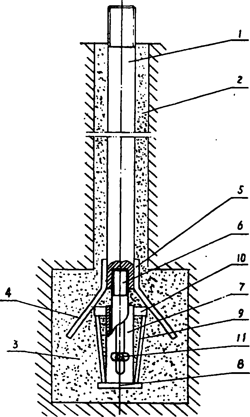
[0036] Such as image 3 As shown, the present embodiment includes an anchor rod 1 arranged in an anchor hole 2, and is characterized in that an anchor head 4 is set under the anchor rod 1, which includes a sliding rod 7 and a stressed pull rod 5, and the stressed pull rod 5 can be used under external force Stretch under action, be located at the anchor rod 1 bottom, can establish one or more than one, be directly welded on the anchor rod 1 or be fixed on the anchor rod 1 by screw. Below the anchor rod 1, a sliding rod 7 is provided, which is placed in the anchor reaming hole 3 provided below the anchor hole 2. The sliding rod 7 is tubular, and its pipe wall is symmetrically provided with a long chute. The lower end of the upper sliding rod 6 is sleeved in the lower end of the lower sliding rod 7, and the pin rod 11 is fixed on the lower end of the upper sliding rod 6, and can pass through the chute of the lower sliding rod 7, driving the upper sliding rod 6 to move up and down...


PUM


Abstract

The present invention relates to an anchoring method, and is characterized by that under the anchor hole in which an anchor bar can be placed an anchor enlarged hole is cut, and in the anchor enlarged hole an anchor head which and rock-soil can produce end resistance between them is placed, and after the anchor head and anchor bar are connected, the concrete can be grouted. Said invention provides the condition required for anchor bar and anchor head structure. Said invented end load-bearing anchor bar includes anchor bar, its lower portion is equipped with lower sliding bar and forced pulling bar which can be opened, and also includes upper sliding bar, lower support bar and supporting plate, etc. It can fully utilize end resistance of rock-soil to greatly raise anchoring force.

Description

Technical field: [0001] The invention relates to the field of building foundations, in particular to the design improvement of an anchoring method and an anchoring piece. Background technique: [0002] At present, the design and construction methods of bolts at home and abroad are carried out according to the force form of pure friction (side resistance), and the side resistance of the rock and soil is what provides the reaction force for the bolt. According to this traditional design method and theory, the bolt material consumption is huge, the engineering cost is high, but the anchoring force is very small; if the required anchoring force is large, the length of the anchoring rod is very long, and the anchoring force is unstable. and loss over time. Invention content: [0003] The technical problem to be solved by this invention is how to increase the contact area between the anchor rod and the rock and soil, so that the anchor rod can not only be affected by the side r...

Claims


Application Information

Patent Timeline
Patent Type & Authority Patents(China)
IPC IPC(8): E02D5/80
Inventor 张百全
Owner 张百全
Why Eureka
Try Eureka