Liquid-cooled crystallizer for continaous casting of metals

A crystallizer and crystallizer plate technology, applied in the field of liquid-cooled crystallizers, can solve problems such as small static friction of elastic components

Inactive Publication Date: 2007-02-14
KME GERMANY GMBH & CO KG
View PDF5 Cites 2 Cited by
  • Summary
  • Abstract
  • Description
  • Claims
  • Application Information

AI Technical Summary

Problems solved by technology

[0003] The disadvantage of this solution is that when a steel elastic ring is used, there is not a small amount of static friction between the elastic elements.

Method used


Image

  • Liquid-cooled crystallizer for continaous casting of metals
  • Liquid-cooled crystallizer for continaous casting of metals
  • Liquid-cooled crystallizer for continaous casting of metals

Examples


Embodiment Construction

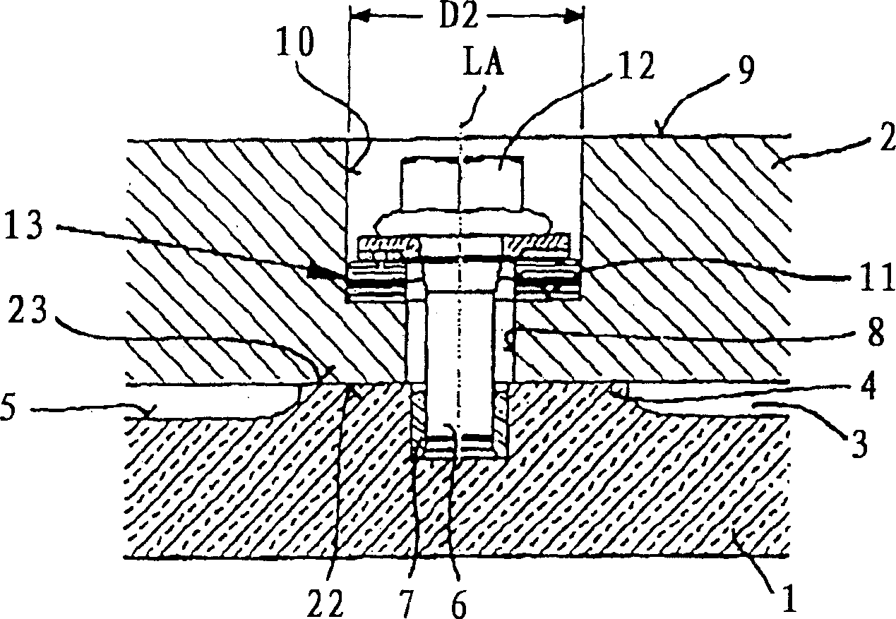
[0022] figure 1 shows a cross-section of the connection area of ​​a mold plate 1 made of copper or a copper alloy, which is fastened on the rear side to a carrier plate 2 . The carrier plate 2 can not only be an adapter plate but also be a component of a water tank not further shown in the figures.

[0023] In the present exemplary embodiment, a cooling gap 3 through which a coolant flows is formed between the mold plate 1 and the support plate 2 . It extends between platforms 4 arranged at a distance from one another, which themselves protrude island-like from the coolant side 5 of the mold plate 1 . In the platform 4 shown in the figure, a bolt 6 is screwed into the center. The bolt 6 engages in a threaded bush 7 in the platform 4 . The bolts 6 pass with play through the through-holes 8 in the carrier plate 2 . The through-hole 8 widens in diameter in the direction of the rear side 9 of the carrier plate 2 into a cylindrical down-hole 10 . In the radially extending hole...


PUM

PropertyMeasurementUnit
friction coefficientaaaaaaaaaa

Abstract

A liquid-cooled mold for the continuous casting of metals, including mold plates made of copper or a copper alloy, which are supported at their rear on supporting plates by the use of a plurality of bolts. The bolts have bolt heads in the region of the backsides of the supporting plates facing away from the mold plates. Between the bolt heads and the supporting plate an articulation system making possible relative motion between the mold plate and the supporting plates is incorporated, having two articulation members, between which a sliding element is undetachably embedded.

Description

technical field [0001] The invention relates to a liquid-cooled crystallizer for metal continuous casting. Background technique [0002] A metal continuous casting mold is known from DE 19581604 T1, in which a uniformly thick mold plate made of copper or copper is connected to a support plate made of steel by means of a plurality of screws. Due to the heat-induced expansion of the mold plate during the pouring operation, especially when the bolts are short, this leads to non-negligible bending and tensile stresses on the bolts. Depending on how the bolts are fastened to the mold plate, this can lead to failure of the welded joint for welded bolts or overloading of the threads for screwed-in bolts. In order to avoid this situation, it is stipulated in DE19581604T1 that the crystallizer plate and the support plate are connected with each other by bolts in a sliding structure, so that the mold plate can move three-dimensionally relative to the support plate. This is achieved ...

Claims


Application Information

Patent Timeline
Patent Type & Authority Patents(China)
IPC IPC(8): B22D11/04B22D11/055B22D11/059B22D11/22
CPCB22D11/055B22D11/059B22D11/22
Inventor 格哈德·胡根许特托马斯·罗尔夫迪特马尔·科尔贝克汉斯-京特·沃布克
Owner KME GERMANY GMBH & CO KG
Why Eureka
Try Eureka