Cylinder stripper

A technology of rollers and guide rollers, used in cleaning devices, transportation and packaging, conveyor objects, etc., can solve the problems of different material removal, wear, uneven scraping ability, etc., and achieve the effect of close contact

Inactive Publication Date: 2007-04-11
汉斯-奥托·施瓦茨
View PDF3 Cites 0 Cited by
  • Summary
  • Abstract
  • Description
  • Claims
  • Application Information

AI Technical Summary

Problems solved by technology

However, the scraping edges of these parts are subject to severe wear, especially at high conveyor speeds
In addition to this, the amount of material removed is very different on the scraping edge, so that the scraping edge shows an irregular change in direction and the scraping capacity is not uniform

Method used


Image

  • Cylinder stripper
  • Cylinder stripper
  • Cylinder stripper

Examples


Embodiment Construction

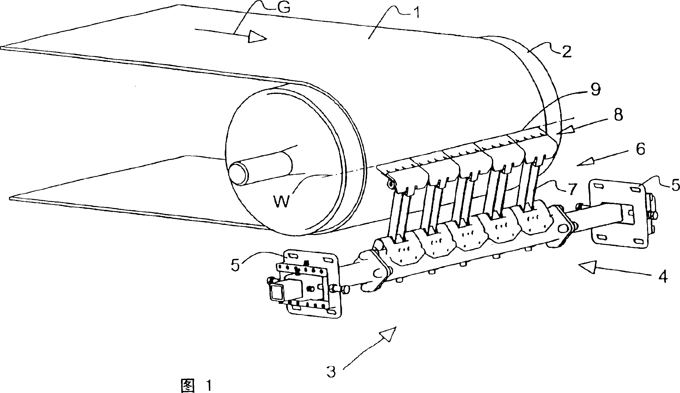
[0064] In the figure, a conveyor belt 1 is arranged around a roller 2 (drive roller and / or guide roller), which rotates around the roller 2 in the direction of conveyor belt travel indicated by arrow G, in this case at a wrap angle of approximately 90°. The drum 2 is usually mounted rotatably in a frame (not shown) of a belt conveyor.

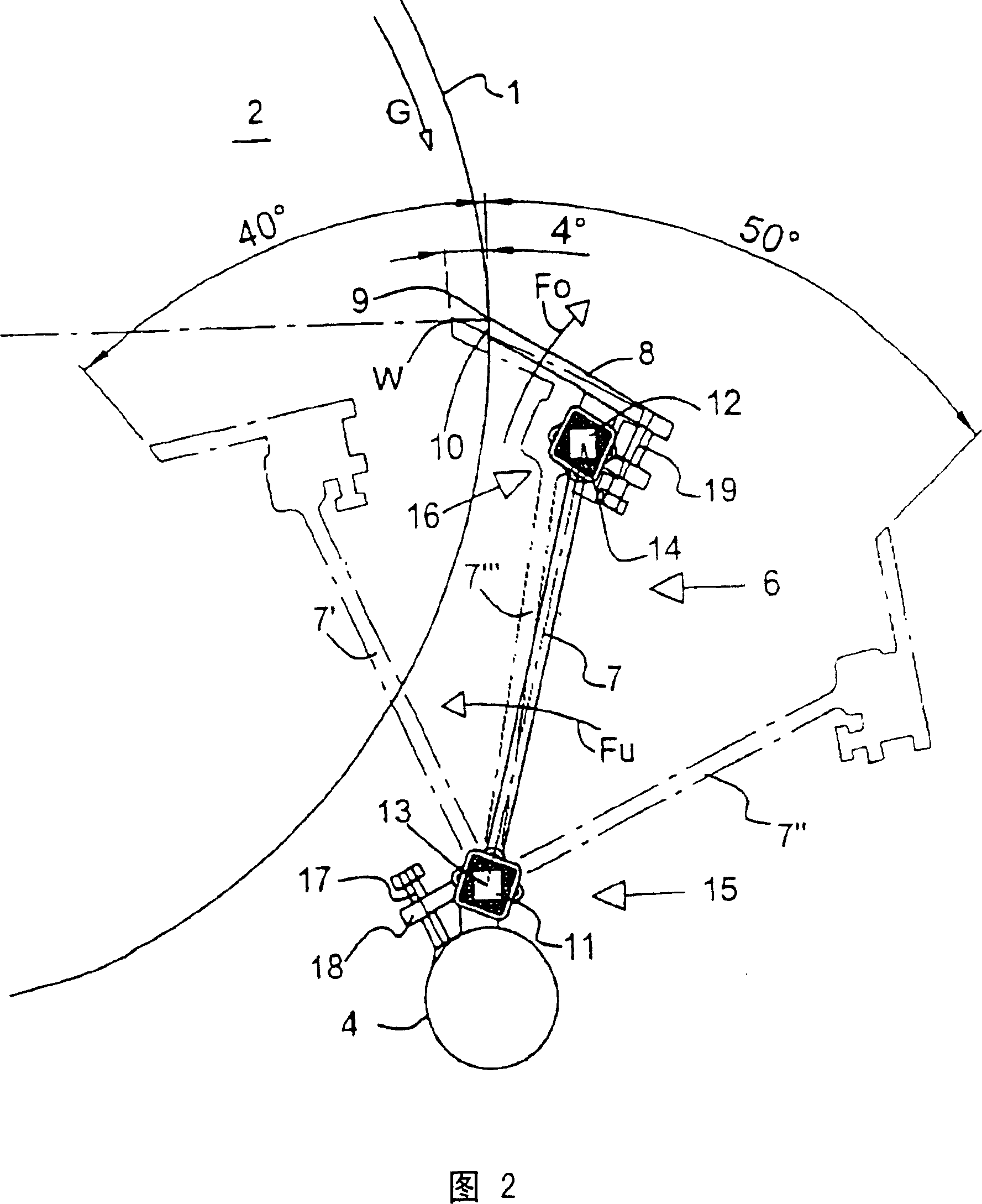
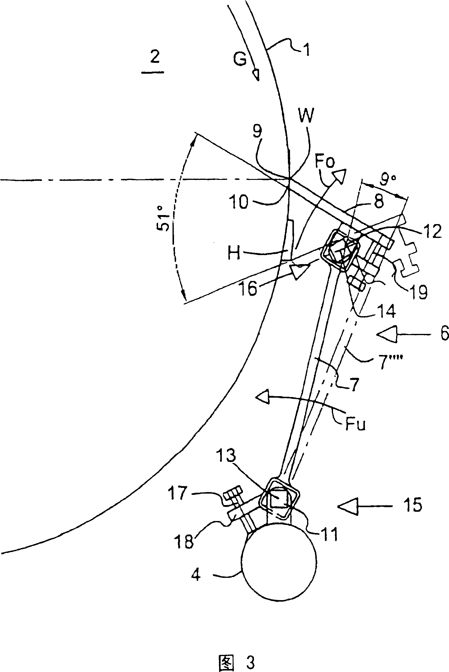
[0065]At the head of the conveyor belt 1 is provided a device 3 as a pre-scraper for scraping dirt off the conveyor belt 1 . The system frame 4 on which five scraping elements 6 are arranged next to each other in a row is moved in the frame of a belt conveyor (not shown) at its two ends by means of side frames 5 . Each scraping member 6 is supported on the system support 4 with a sheet-like support 7 and above (“above” or “horizontal” or similar expressions, here and below refer in principle to the use position of the scraping member 6) with a scraper Sheet 8, it with scraping edge 9 on the so-called 3 o'clock position along a dotted line of a...


PUM


Abstract

The present invention departs from an apparatus for stripping dirt off belts in conveyor belt assemblies in the area of a drive and/or head pulley of the belt comprising a system carrier to be attached to a belt carrier frame, at which at least one stripping element is arranged, the stripping element having a stripping lamella mounted on a lamella holder, the stripping lamella contacting the belt in a peeling position, and wherein the stripping element has a bottom swivel mount coupled to the lamella holder and having a horizontal swivel axis-indications such as 'horizontal' or the like here and in the following principally refer to the position of use of the stripping element as well as a spring means acting to press the stripping lamella on the lamella holder against the belt in such a form and arrangement that the lamella holder in the stripping position of the stripping lamella is swivelled about the horizontal swivel axis in a spring loaded fashion, and when obstructions fast adhering to the belt impact on the stripping lamella, the lamella holder may be easily deflected and returned back to the working position on the belt. In order for the stripping device to be able to be used in the pulley area of the belt at least as a pre-stripper having uniform stripping performance and long tool lives can be achieved also with high belt velocities associated with correspondingly great material amounts, it is provided that the stripping lamella is swivel mounted at the lamella holder by a top swivel mount having a horizontal swivel axis and is held by a top spring means in a spring biased fashion whose spring action-with respect to the bottom swivel mount and its spring means-is in the counter sense.

Description

technical field [0001] The invention relates to a device for scraping off dirt on a conveyor belt in a conveyor belt conveyor system at the location of a drive roller and / or a guide roller of the conveyor belt, which [0002] - have a system bracket that should be fastened to the conveyor machine support frame, [0003] - at least one scraping member is provided on the support, [0004] - wherein the scraping member has a scraping blade mounted on a sheet-like support, [0005] - it rests planing against the conveyor belt in scraping position, [0006] - and wherein the scraping member has a lower swivel hinge connected to the plate support, the hinge has a horizontal axis of rotation, such as "horizontal" or the like, here and below in principle referring to the use position of the scraping member , [0007] - and have a spring device for pressing the scraper blade against the conveyor belt to act on the blade support, so designed and arranged that [0008] - the blade s...

Claims


Application Information

Patent Timeline
Patent Type & Authority Patents(China)
IPC IPC(8): B65G45/16
CPCB65G45/16
Inventor 汉斯-奥托·施瓦茨
Owner 汉斯-奥托·施瓦茨
Why Eureka
Try Eureka