
Noise reduction structure of porous plate

A technology of perforated plate and structure, which is applied in the direction of sound-absorbing devices, sound-generating devices, pipes/pipe joints/fittings, etc., which can solve the problems of performance degradation, noise reduction performance, and large overall volume, and achieve high noise reduction effect.

Active Publication Date: 2007-04-18
KOBE STEEL LTD +1
View PDF8 Cites 0 Cited by
  • Summary
  • Abstract
  • Description
  • Claims
  • Application Information

AI Technical Summary

Problems solved by technology

[0006] However, in the structure of the silencing pipe A of the above-mentioned Non-Patent Document 1, there is a problem that the porous silencing material itself changes or deteriorates over time due to flow velocity changes, temperature changes, dew condensation, etc. down, and into devices such as compressors, turbines, pumps, etc., thereby significantly degrading the performance of these devices or causing them to fail
In addition, when disposing of the sound-absorbing pipe, since porous sound-absorbing materials such as glass wool become industrial waste, costs for separation and disposal are incurred
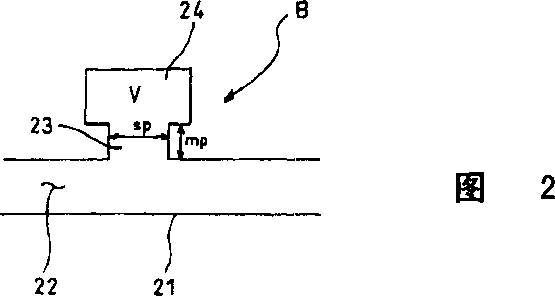
In addition, in the structure of the resonance silencer B of the above-mentioned non-patent document 1, there is the following problem: since only the noise of a specified frequency can be eliminated, in order to obtain the noise reduction effect in a relatively large frequency range, it is necessary to connect and adjust multiple components of different frequencies. A resonance muffler, in addition, it is necessary to set up an amplification chamber surrounding the small hole of the piping line outside the piping line, and the overall volume is relatively large
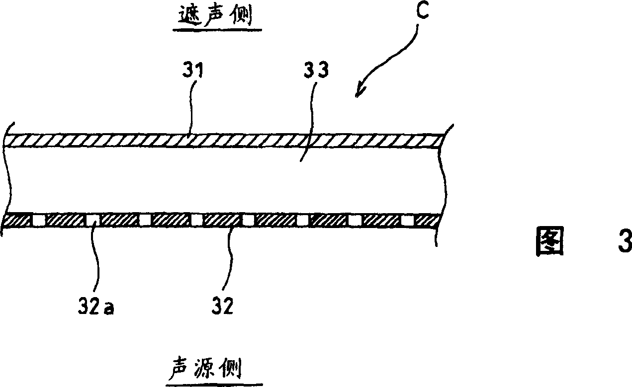
Furthermore, in the configuration of the porous soundproof structure C of the above-mentioned Patent Document 2, there is a problem that generally, the smaller the opening, the higher the sound attenuation performance. , oil droplets, and liquid droplets are more likely to clog the opening, which reduces the sound attenuation performance

Method used


Image

  • Noise reduction structure of porous plate
  • Noise reduction structure of porous plate
  • Noise reduction structure of porous plate

Examples


Embodiment Construction

[0030] Embodiments of the invention will be described below. 4a and 4b are diagrams showing a first embodiment of the present invention. 4a and FIG. 4b, the noise reduction structure D has a cylindrical piping 41, a porous plate 42 extending in the axial direction of the piping 41 inside the piping 41 and dividing the cross-section of the piping 41. The piping path 41 partitioned by the plate 42 is partitioned by a partition plate 43 into a plurality of small chambers 44 in the axial direction of the piping path.

[0031] The piping line 41 is formed in the middle of the air supply or exhaust piping lines of compressors, turbines, pumps, power machines, and the like. The piping path 41 has a long shape with a circular cross section. Gas that is impacted by air supply or exhaust passes through the piping line 41 . The perforated plate 42 has a plate shape and is arranged parallel to the axial direction of the piping path 41 . With this arrangement, the perforated plate 42 d...


PUM


Abstract

Provided is a small noise reduction structure capable of exhibiting full noise reduction performance over a wide frequency bandwidth. The noise reduction structure D comprises a cylindrical duct 41; a perforated panel 42 extended inside the duct 41 along the axial direction of the duct 41 and positioned to define the duct cross section of the duct 41; and partition panels 43 by which the duct 41 defined by the perforated panel 42 is axially partitioned into a plurality of cells 44. The intervals at which the partition panels 43 are installed are adjusted so that b F16L 55 / 02 F01N 1 / 02 7 13 1 2004 / 5 / 21 1573199 2005 / 2 / 2 1311186 2007 / 4 / 18 2007 / 4 / 18 2007 / 4 / 18 Kobe Steel Ltd Kabushiki Kaish Japan Utsuno Hideo Yamaguchi Zenzo Tsugihashi Kazuki Komura Kazyo Kimura Yasumasa Honke Koichi wen dapeng yang songling 72001 The Company Ltd. of the Chinese Patent Agency (Hong Kong) Zi Building 22, Yingjun Centre, No.23, Gangwan Road, Hong Kong Wanzi Japan 2003 / 5 / 23 146579 / 03

Description

technical field [0001] The present invention relates to a technology of a sound-absorbing structure in a piping line for air supply or exhaust between devices or between devices. Background technique [0002] The art of sound-absorbing construction is well known in the prior art. For example, there are techniques disclosed in Non-Patent Document 1 and Patent Document 2. In this non-patent document 1, the silencer pipe A shown in FIG. 1, the resonance silencer B shown in FIG. 2, etc. are disclosed. The silencing pipe A shown in FIG. 1 is composed of a pipe 11 having a quadrangular cross section and a porous silencing material 12 . In this sound-absorbing structure, a porous sound-absorbing material 12 (for example, glass wool or metal fiber) is arranged with a certain thickness along the inner wall of the pipe 11 in the pipe 11 , and sound energy is dissipated by the porous sound-absorbing material 12 . The resonance silencer B shown in FIG. 2 is composed of a piping line ...

Claims


Application Information

Patent Timeline
IPC IPC(8): F16L55/02F01N1/02G10K
CPCF01N1/023
Inventor 宇津野秀夫山口善三次桥一树小村一雄木村康正本家浩一
Owner KOBE STEEL LTD
Learn More