Eureka AIR delivers breakthrough ideas for toughest innovation challenges, trusted by R&D personnel around the world.

Diaphragm regulating method of computer lamination contrast and computer lamination contrast apparatus

A tomography, computer technology, applied in X-ray equipment, computed tomography scanners, using diaphragms/collimators, etc., can solve problems such as complex structures, achieve good results, and reduce total radiation burden.

Inactive Publication Date: 2007-05-16
SIEMENS AG
View PDF4 Cites 3 Cited by
  • Summary
  • Abstract
  • Description
  • Claims
  • Application Information

AI Technical Summary

Problems solved by technology

[0009] The disadvantage of this device and this method for aperture adjustment is that additional special position detectors are required and their construction is more complex since these detectors have to determine the radiation position distribution thereon

Method used


Image

  • Diaphragm regulating method of computer lamination contrast and computer lamination contrast apparatus
  • Diaphragm regulating method of computer lamination contrast and computer lamination contrast apparatus
  • Diaphragm regulating method of computer lamination contrast and computer lamination contrast apparatus

Examples


Embodiment Construction

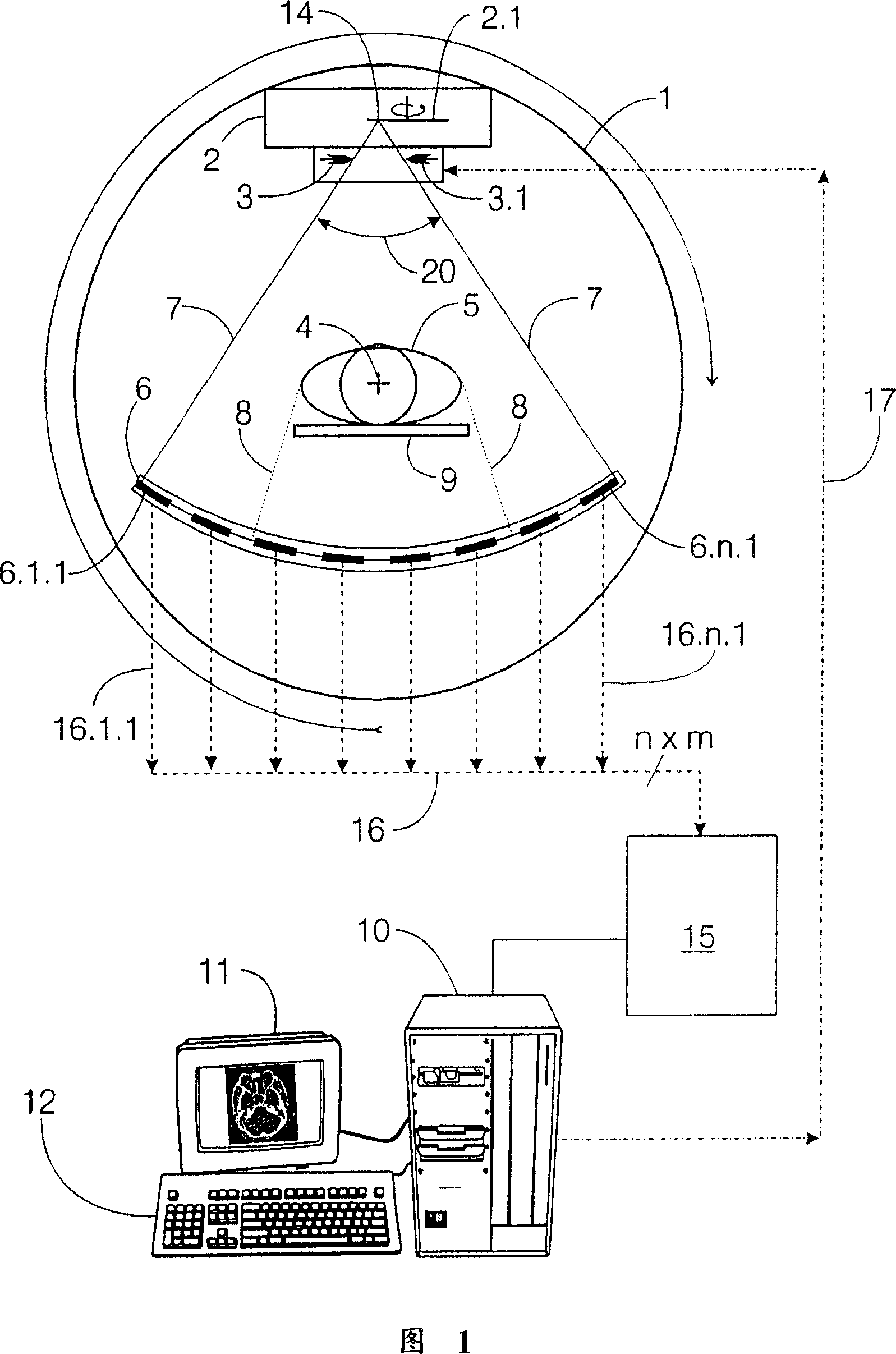
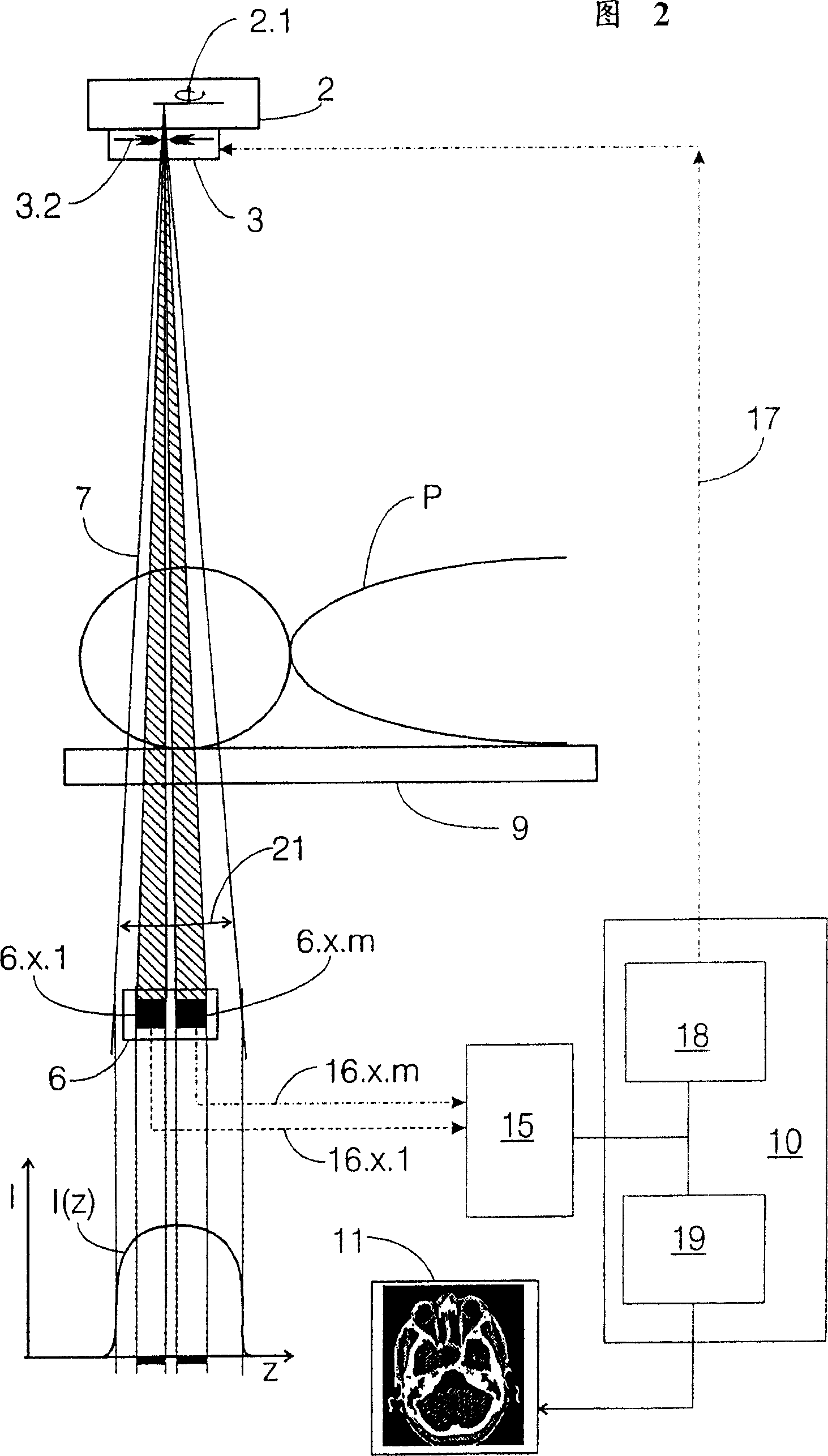
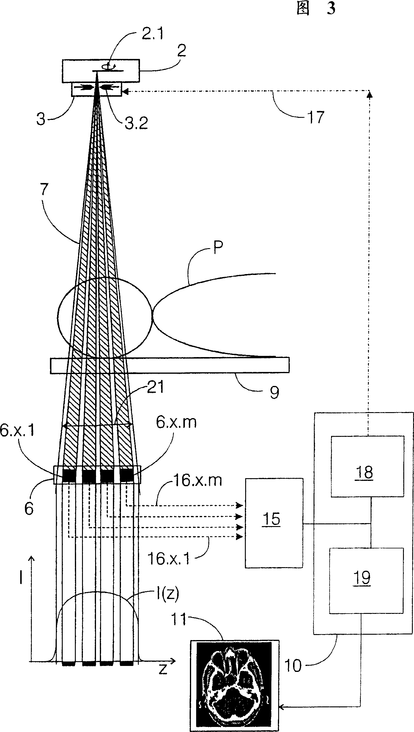
[0035] In FIG. 1 , a schematic diagram according to an embodiment of the invention shows a computed tomography device, here a cross-sectional view of an X-ray computed tomography device. This section is perpendicular to the system axis 4 , about which the measuring unit or the gantry of the computed tomography system can be rotated during the generation of the tomographic images. The measuring unit consists of an x-ray tube 2 which together with a rotating anode 2.1 is used to generate x-rays. The x-rays of the rotating anode 2 are limited and regulated by means of a diaphragm adjustment device 3 with an integrated diaphragm 3.1 in the transverse direction and a diaphragm 3.2 in the longitudinal direction. Below the x-ray tube 2 is a detector with a detector region 6, the array consisting of a plurality of detectors 6.1.1 to 6.n.m in m rows and n columns. In this figure, however, the downstream row of detectors cannot be recognized directly from this sectional view, but only ...


PUM

PropertyMeasurementUnit
angleaaaaaaaaaa

Abstract

In a method for diaphragm regulation in a computed tomography system and a computed tomography system with diaphragm regulation and a multi-line detector, the image detector signals are utilized for generating a setting signal for the diaphragm.

Description

technical field [0001] The invention relates to a method for adjusting the diaphragm of computed tomography, wherein, a measuring unit composed of a radiation source and a radiation receiver, and a measuring unit arranged between the radiation source and the radiation receiver and used to carry the The object holder of the object is mutually rotated about the system axis, and by means of a computer system, the intensity distribution of the radiation fan-shapedly emitted from the radiation source to the radiation receiver is measured by means of a detector area, wherein the detector area has at least one row arranged at the focal point of the radiation source Surrounding radiation-sensitive image detectors to calculate the attenuation distribution in at least one plane of the object to be examined, the object shielding only a part of the fan-shaped radiation of the radiation receiver. [0002] Furthermore, the invention relates to a computed tomography system with a movable mea...

Claims


Application Information

Patent Timeline
Patent Type & Authority Patents(China)
IPC IPC(8): A61B6/03H05G1/08G01N23/04A61B6/06G01T1/00G21K1/04G21K5/02
CPCA61B6/542A61B6/032A61B6/4021A61B6/06
Inventor 沃尔夫冈·布雷塞尔海因里希·沃尔施拉格尔
Owner SIEMENS AG
Why Eureka
Eureka Blog
Learn More