Casting tube, clamping device for a casting tube and casting machine

A technology for casting equipment and pouring nozzles, which is applied in the direction of casting equipment, metal processing equipment, casting molten material containers, etc., can solve problems such as unsatisfactory, expensive solutions, etc., to reduce the occurrence and/or expansion of cracks, The effect of enhancing the ability to resist cracking

Inactive Publication Date: 2007-07-11
VESUVIUS GRP SA
View PDF9 Cites 5 Cited by
  • Summary
  • Abstract
  • Description
  • Claims
  • Application Information

AI Technical Summary

Problems solved by technology

These solutions are expensive and not entirely satisfactory

Method used


Image

  • Casting tube, clamping device for a casting tube and casting machine
  • Casting tube, clamping device for a casting tube and casting machine

Examples


Embodiment Construction

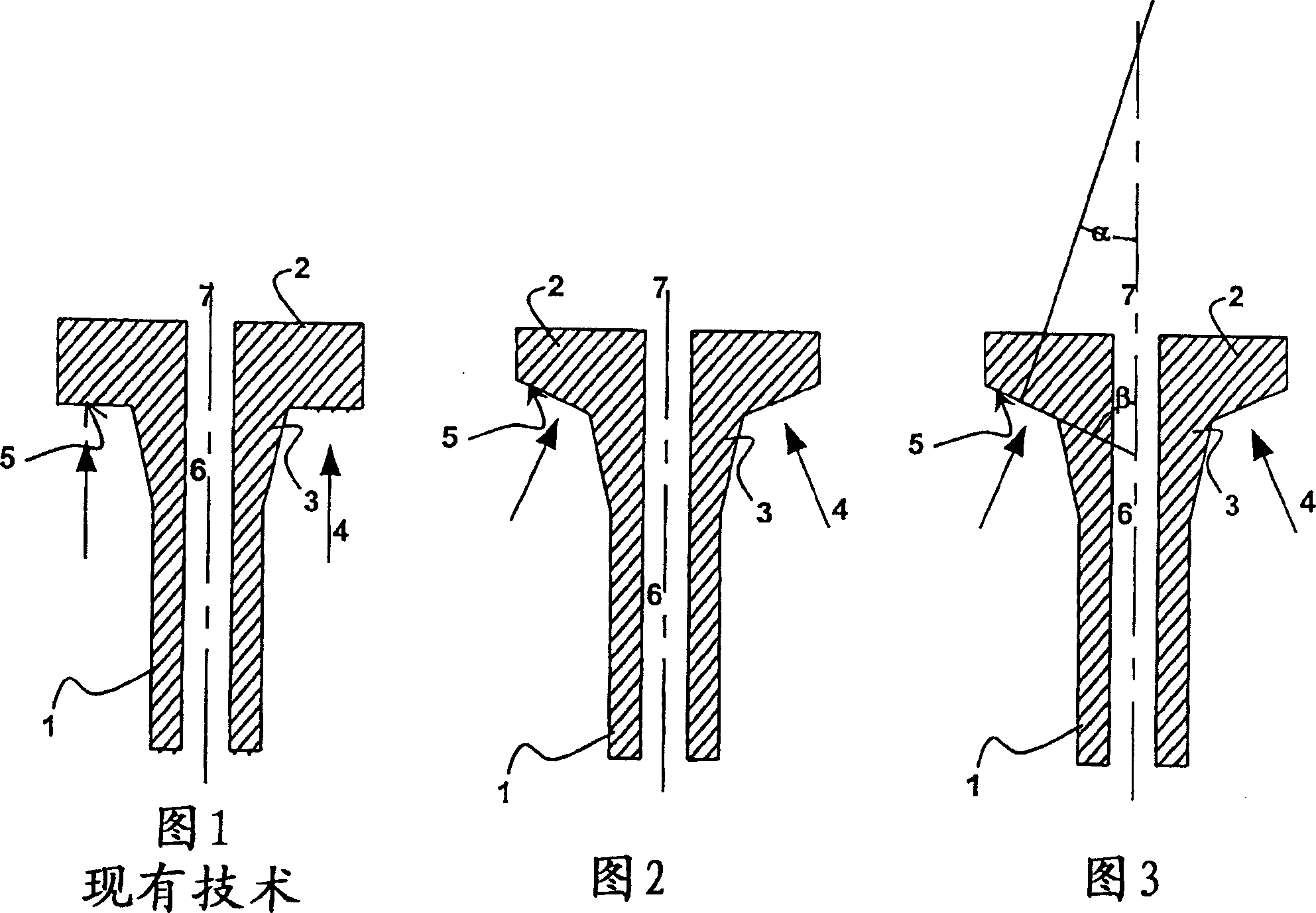
[0042] Figure 1 shows a pouring nozzle (1) according to the prior art, said nozzle comprising a plate (2) and a tubular part (3). The angle β formed between the planar bearing surface (5) and the runner axis (7) is 90°. The thrust (4) is vertical, parallel to the axis of the sprue (7). In the prior art, stresses generated in the pouring nozzle are responsible for the formation of cracks at the tip of the tubular portion (3).

[0043] Accompanying drawing 2 and accompanying drawing 3 show pouring nozzle (1) of the present invention. The plate (2) of the nozzle (1) is beveled in a specific manner. The angle β formed by the planar support surface (5) ranges from 20° to 80°, so that there is no need to increase the amount of material of the plate (2).

[0044] Figure 3 shows the angles α and β. The angle α formed between the resultant thrust force and the runner axis is 21°. The angle β formed between the planar bearing surface and the axis of the runner is 69°.

[0045] Acc...


PUM


Abstract

The pouring tube (1) comprising a tubular section (3) with a pouring channel (6) and a top plate (2) with an aperture has flat thrust surfaces (5) beneath the plate that form an angle of 20 - 80 degrees, and preferably close to 45 degrees, with axis (7) of the pouring channel. The pouring tube is set in a tube feed and changer with springs applying a thrust force at 30 - 60 degrees, and preferably 45 degrees to the tube channel's axis.

Description

technical field [0001] The invention relates to a pouring nozzle for conveying molten metal from an upper metallurgical vessel to a lower metallurgical vessel. In particular, the invention relates to a pouring nozzle made of refractory material for conveying molten steel from the tundish to the ingot mold, or alternatively, from the ladle to the tundish. Background technique [0002] Spout nozzles are used to convey molten metal from one metallurgical vessel to another while protecting the metal from chemical attack and thermal insulation from the surrounding air. These nozzles are wear elements and these wear elements are subjected to high pressure. So to a certain extent, their service life will limit the casting time. Devices suitable for inserting and / or removing pouring nozzles have been recently described in the prior art to solve this problem (see eg European patents 192,019 and 441,927). For example, once the outer wall of the sprue adjacent to the meniscus corrode...

Claims


Application Information

Patent Timeline
Patent Type & Authority Patents(China)
IPC IPC(8): B22D41/50B22D41/28B22D41/56
CPCB22D41/56B22D41/28B22D41/50
Inventor 埃里克·汉泽斯特凡娜·塔比里奥
Owner VESUVIUS GRP SA
Why Eureka
Try Eureka