Electric booster device for electric booster vehicle

A technology of electric power assist and vehicles, which is applied in the direction of electromechanical devices, electric components, vehicle components, etc.

Inactive Publication Date: 2007-07-25
HONDA MOTOR CO LTD
View PDF6 Cites 1 Cited by
  • Summary
  • Abstract
  • Description
  • Claims
  • Application Information

AI Technical Summary

Problems solved by technology

[0003] As mentioned above, in the drive device of the prior art, since the controller case is formed by protruding a part of the motor case downward, there is a problem of increasing the size of the drive device.
In addition, in the existing drive unit, there is no special consideration for miniaturization

Method used


Image

  • Electric booster device for electric booster vehicle
  • Electric booster device for electric booster vehicle
  • Electric booster device for electric booster vehicle

Examples


Embodiment Construction

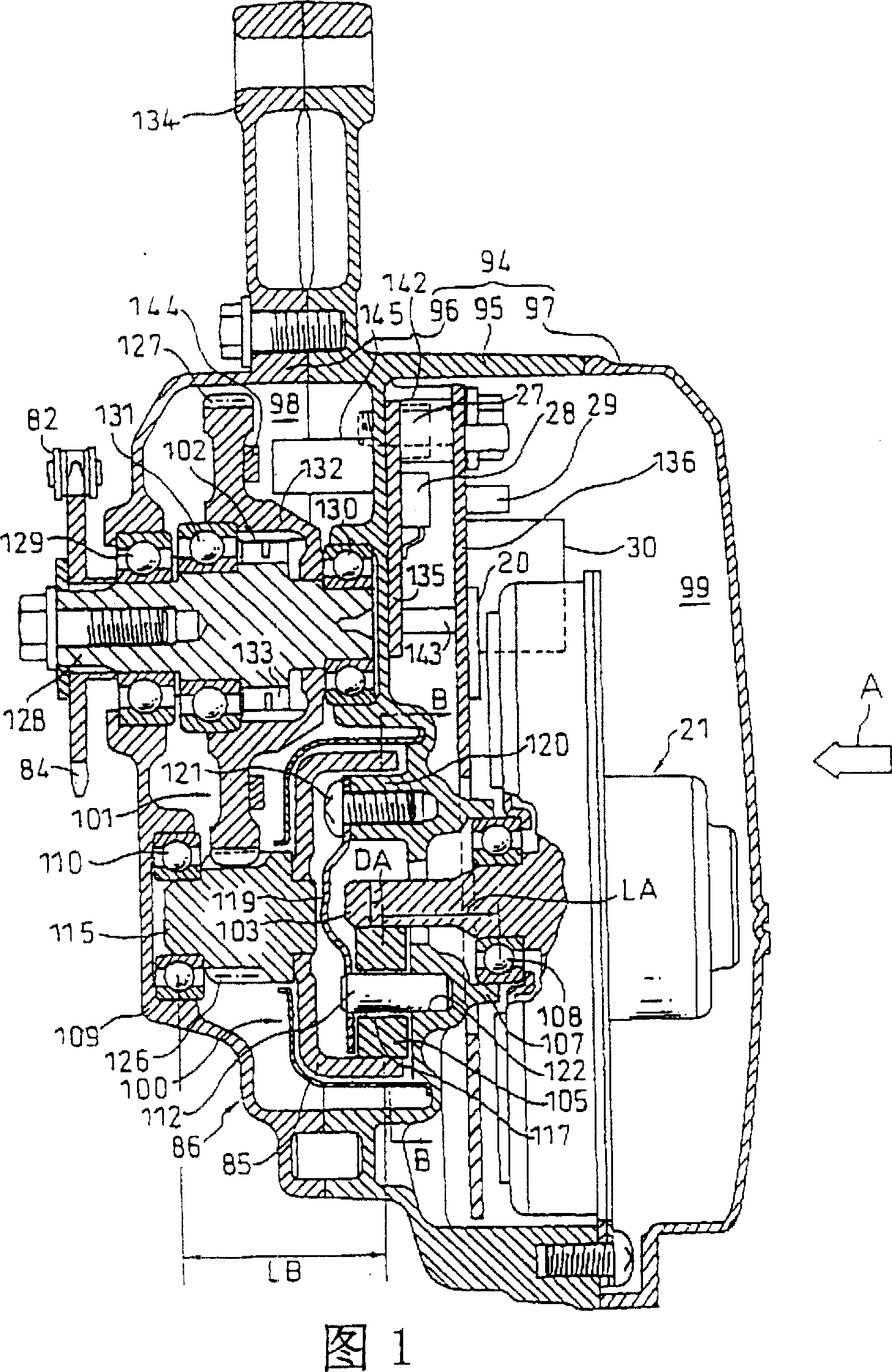
[0032] The present invention will be described in detail below with reference to the accompanying drawings. Fig. 4 is a side view of an electric power assist bicycle provided with a miniaturized electric power assist device of the present invention. In this figure, a bicycle frame 67 has a head tube 68 located at the front of the bicycle, a down tube 69 extending rearward and downward from the head tube 68, and a bicycle frame fixed to the rear end of the down tube 69 and raised slightly upward and backward. Seat column 71. A front fork 72 is steerably supported on the head pipe 68 , and a front wheel 73 is pivotally supported on the lower end of the front fork 72 . A steering handle 74 is provided at the upper end of the front fork 72 .

[0033] A rear wheel 78 serving as a drive wheel is pivotally supported on rear ends of a pair of left and right rear forks 70 extending rearward from the seat post 71 . In addition, a pair of left and right stays 77 are connected to the r...


PUM


Abstract

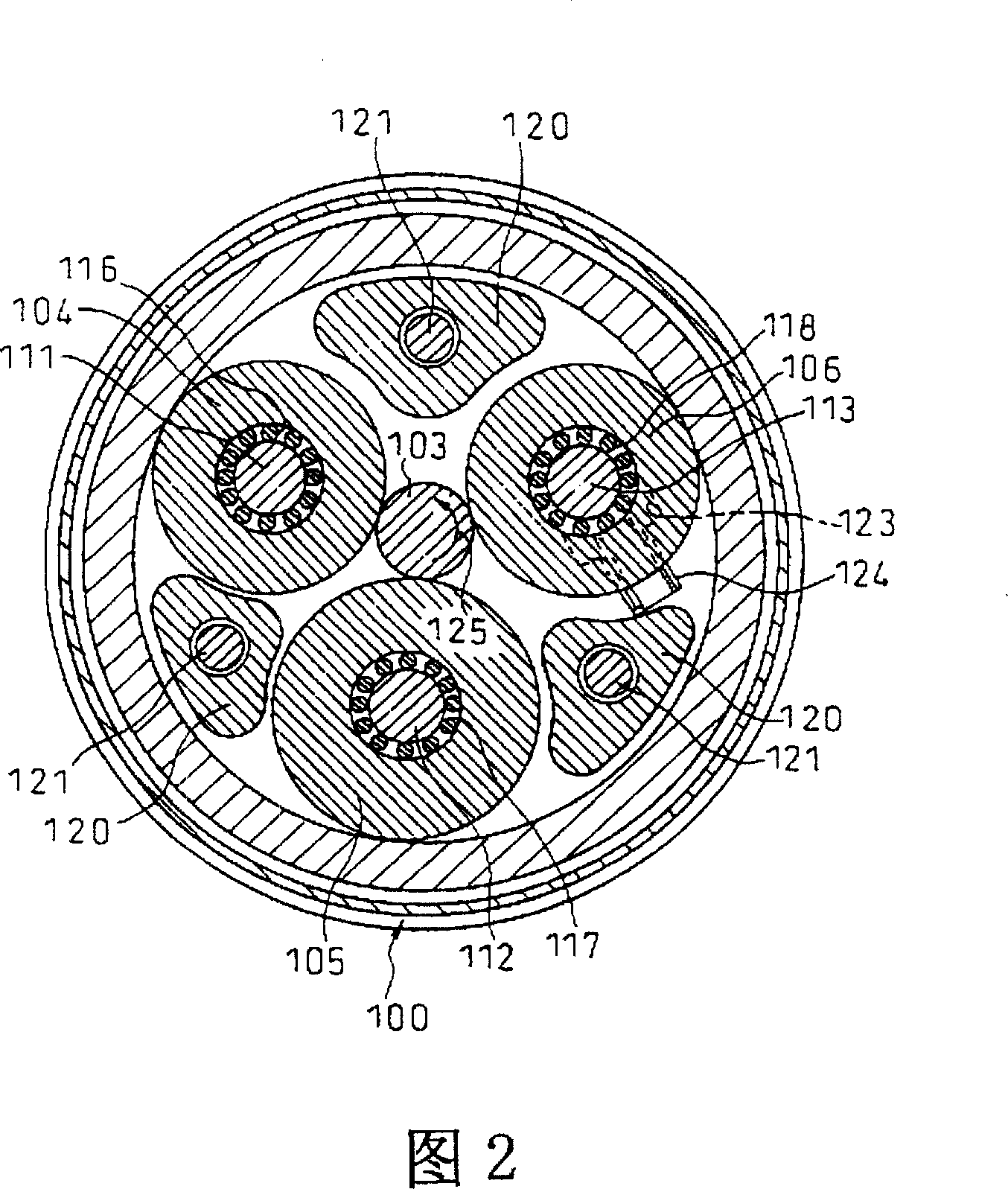
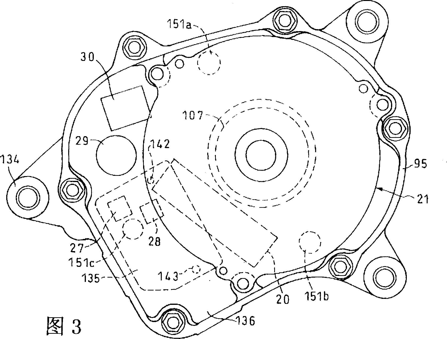
The invention provides a motor-assisted drive unit for a motor-assisted vehicle, which is made as small in size as possible. A first control board (136) on which control devices of a drive motor (21) are mounted is disposed in a casing (94). In this case, the first control board (136) extends in the direction nearly perpendicular to the motor shaft of a motor (21); and at least part of the first control board (136) extends, as seen along the axial direction (A) of the motor (21), to a position at which it is overlapped to the motor (21). The second control board (135) is overlapped to part of the first control board (136). As a result, it is possible to dispose a CPU (20) having a relatively large mounting area on a portion, overlapped to the motor (21), of the first control board (136), and hence to effectively use the inner space of the casing. Further, since the second control board (135) is configured as an aluminum board and is directly mounted on the inner wall of the casing (94), it is possible to effectively transfer the heat generated from a FET and the like mounted on the second control board (135).

Description

technical field [0001] The present invention relates to an electric power assist device for an electric power assist vehicle, in particular to an electric power assist device suitable for use in an electric power assist vehicle that needs to be miniaturized as much as possible and can only provide a small space attached to it. Background technique [0002] In the prior art, vehicles such as bicycles have been provided which detect the pedaling force which is the driving torque of human power, and generate power according to the detected pedaling force by an auxiliary power source (DC motor, etc.) connected to the drive train to assist the pedaling force. An example of an electric power booster that is a drive device including the auxiliary power source is described in JP-A-11-5584, for example. The drive unit is arranged around and behind the crankshaft, and protrudes downward from the motor housing housing the motor to form a controller housing that houses electronic compon...

Claims


Application Information

Patent Timeline
Patent Type & Authority Patents(China)
IPC IPC(8): B62M23/02H02K29/00H02K5/00B62M6/55F16F15/08
CPCY10S310/06B62M6/55B62M6/45B62M6/40B62M6/70
Inventor 坪井正治
Owner HONDA MOTOR CO LTD
Why Eureka
Try Eureka