Air-flow spinner

An air spinning machine and yarn technology, which is applied to spinning machines, open-end spinning machines, continuous winding spinning machines, etc., can solve the problems of complex and expensive design and structure of auxiliary devices, and achieve simple structure, The effect of low cost and low twist coefficient

Inactive Publication Date: 2007-07-25
SAURER GERMANY GMBH & CO KG
View PDF5 Cites 0 Cited by
  • Summary
  • Abstract
  • Description
  • Claims
  • Application Information

AI Technical Summary

Problems solved by technology

[0005] For example in the patent DE19827605A1 described in great detail the design and construction of this auxiliary device is generally more complex and thus more expensive

Method used


Image

  • Air-flow spinner
  • Air-flow spinner
  • Air-flow spinner

Examples


Embodiment Construction

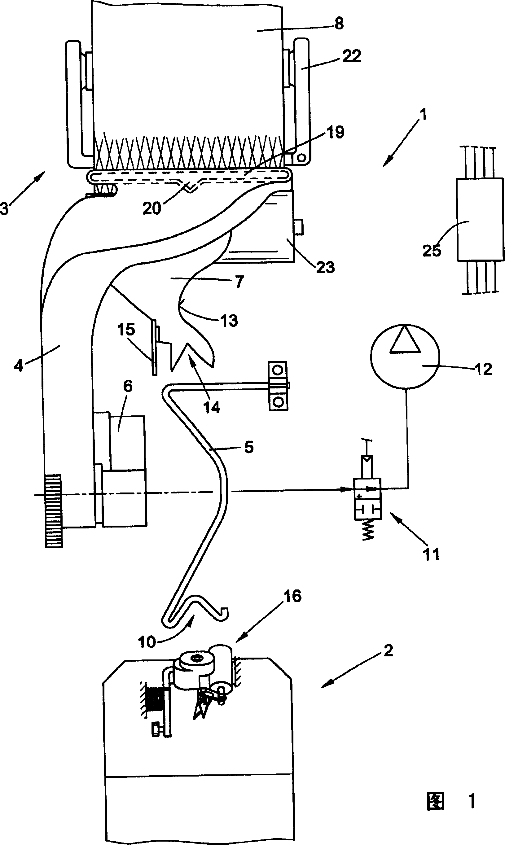
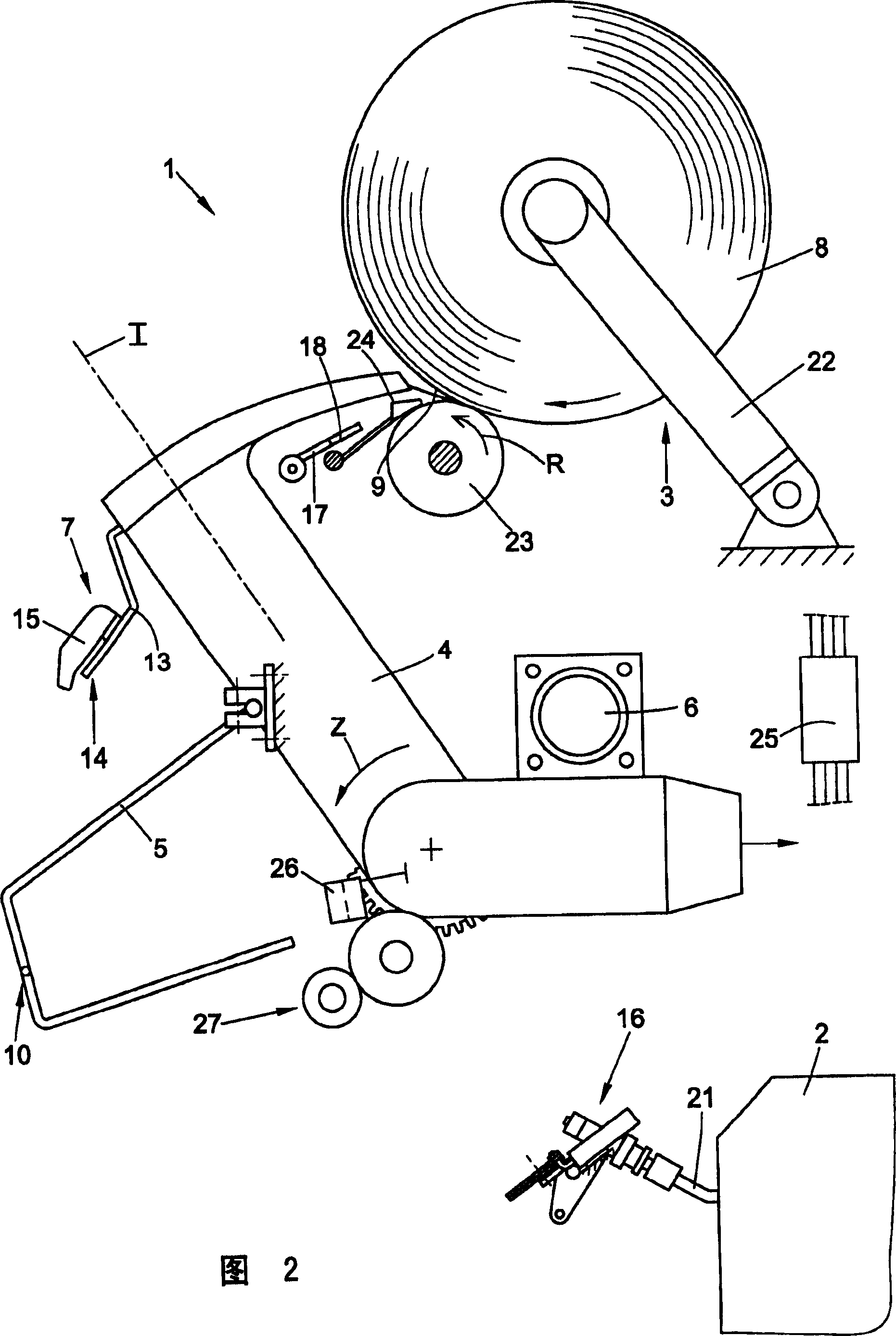
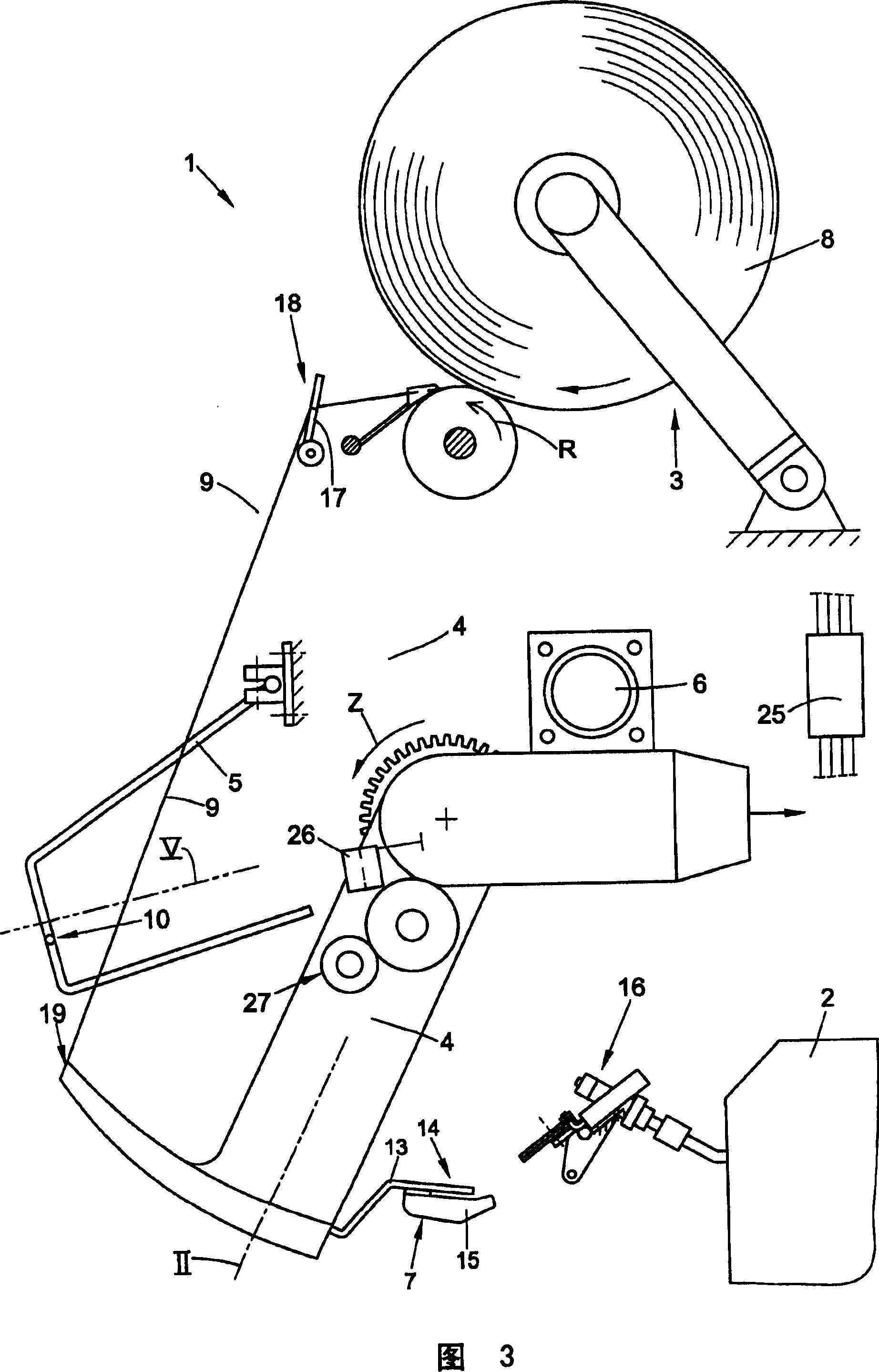
[0032] The working positions of the air spinning machine shown in the front view in FIG. 1 are generally indicated by reference numeral 1 . As shown in the figure, the working positions 1 each have an air spinning device 2 and a winding device 3 which are known per se and are therefore only shown schematically. Furthermore, at each working position 1 there is a piecing mechanism 16 , a yarn breakage detector 26 and a yarn unwinding device 27 . The rotatably mounted piecing mechanism 16 arranged just before the yarn unwinding tube 21 of the air spinning device 2 pre-treats the yarn 9 sucked back by the suction nozzle 4 from the cross-winding bobbin 8, for example after a yarn break, in order to re- connector. Then, the yarn unwinding device 27 returns the prepared yarn 9 to the air spinning device 2 through the yarn unwinding tube 21, where, as known, the yarn is connected to a surrounding fiber loop.

[0033] As usual, the winding device 3 comprises a creel 22 holding a cros...


PUM


Abstract

The invention relates to an air-flow spinner having a plurality of identical work stations, wherein each work station (1) comprises: at least an air-flow spinning device for producing a yarn; a winding device with a creel, a yarn cross-winding device for producing a cross-winding pony roll; a vacuum-chargeable, pivotably seated suction nozzle; a device for preparing a yarn end for piecing again, and a yarn guide device fixed thereon. According to the invention, the yarn guide device and a yarn catch element (7) fixed on the nozzle (4) and being movable by the nozzle cooperatively retrieve the yarn (9) from the cross-winding pony roll (8) and return the yarn to the spinning device (2).

Description

technical field [0001] The present invention relates to air spinning machines. Background technique [0002] For example, as described in the patent DE19836065A1, the air spinning machine usually has a plurality of identical working spindle positions arranged side by side in rows, each of which has an air spinning device and a winding device. This means that, on each working position of the spinning machine, a fiber sliver fed into a can, for example, is spun into yarn by means of an air spinning device, and then the yarn is wound into a yarn by means of a winding device. A cross-wound bobbin. [0003] In addition, yarn is supplied to the working spindles through an auxiliary device that can move along the working spindles of the air spinning machine. When a fault occurs on a working spindle, such as a thread break, the auxiliary device is automatically put into work. In such a case, the auxiliary device is moved to the relevant working position and positioned there and pi...

Claims


Application Information

Patent Timeline
Patent Type & Authority Patents(China)
IPC IPC(8): D01H4/50D01H13/00B65H67/08B65H54/71D01H4/48
CPCB65H67/081B65H2701/31B65H54/71D01H4/50D01H4/48
Inventor P·斯特拉尔藤
Owner SAURER GERMANY GMBH & CO KG
Why Eureka
Try Eureka