Tin ball maker by double electrothermal filament smelting and cutting method
A technology of electric heating wire and preparation machine, which is applied in the direction of circuits, electrical components, electric solid devices, etc., and can solve the problems of complex and expensive equipment
- Summary
- Abstract
- Description
- Claims
- Application Information
AI Technical Summary
Problems solved by technology
Method used
Image
Examples
specific Embodiment approach 1
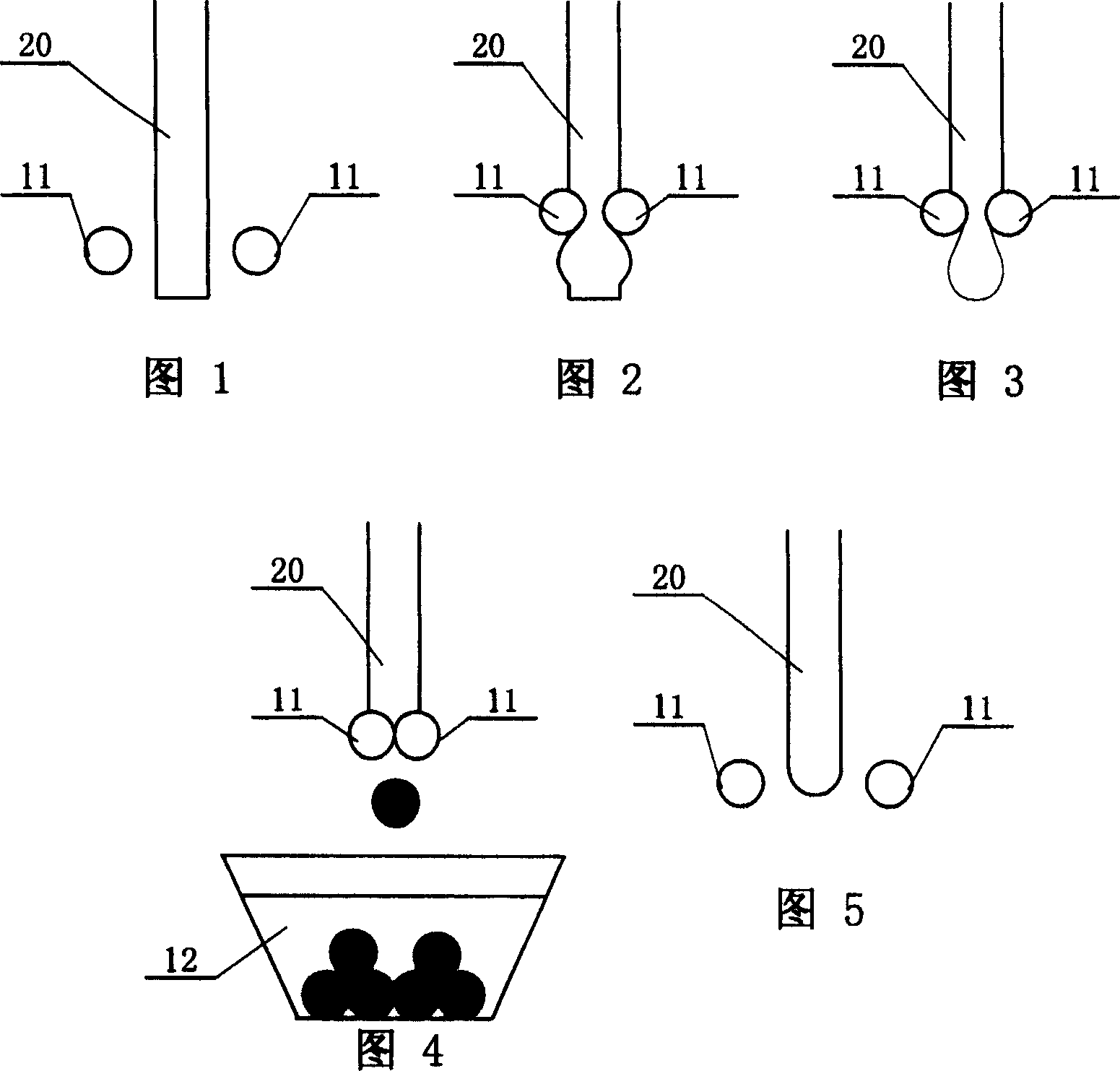
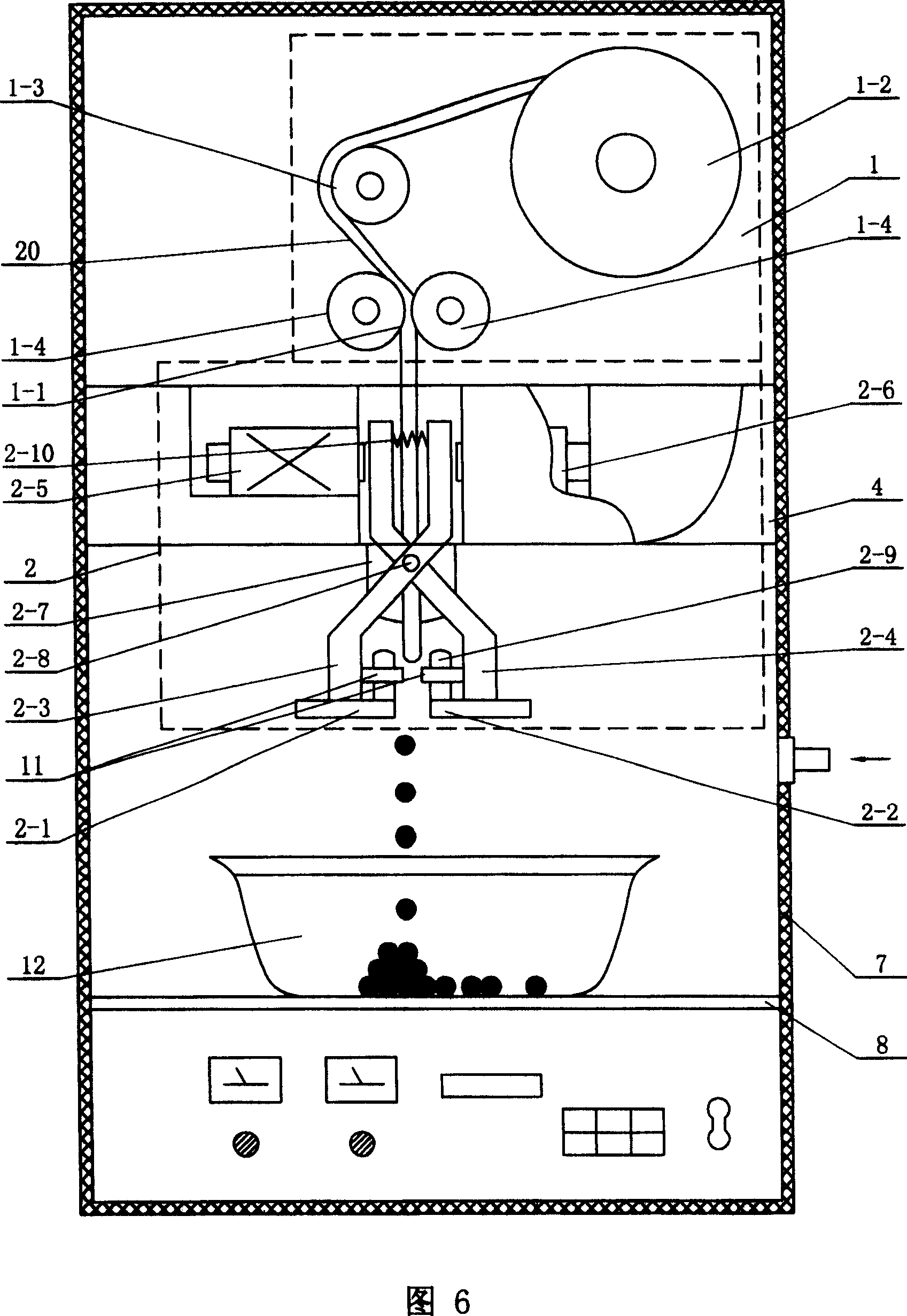
[0005] Specific Embodiment 1: The present embodiment will be specifically described below with reference to FIG. 6 . This embodiment consists of a wire feeder 1, a wire cutting mechanism 2, the same two heating wires 11, a cover body 7, a platform 4 and an oil box 12. The wire feeding machine 1, the wire cutting mechanism 2, the heating wire 11, and the platform 4 and the oil box 12 are all enclosed in the cover body 7, the wire feeder 1 is arranged on the upper part of the cover body 7, the wire cutting mechanism 2 is arranged under the wire feeder 1, and the wire outlet channel 1-1 of the wire feeder 1 is The projection directly below is located in the middle of the two heating wires 11 arranged in parallel in the horizontal direction, and the two heating wires 11 are respectively fixed on the left translation plate 2-1 and the right translation plate of the wire cutting mechanism 2 that can be closed and separated in the horizontal direction 2-2, the wire cutting mechanism ...
specific Embodiment approach 2
[0006] Specific Embodiment 2: The present embodiment will be specifically described below with reference to FIG. 6 and FIG. 7 . The difference between this embodiment and Embodiment 1 is that the wire cutting mechanism 2 consists of a left translation plate 2-1, a right translation plate 2-2, a left hanger arm 2-3, a right hanger arm 2-4, a left arm Square electromagnet 2-5, right side electromagnet 2-6, trunnion frame 2-7, trunnion 2-8, back-moving spring 2-10 and four thermal insulation columns 2-9 are formed, and trunnion frame 2- The upper end of 7 is fixed on the platform 4, the middle part of the left hanger cantilever 2-3 and the middle part of the right hanger cantilever 2-4 are hinged together through the trunnion 2-8, and the upper end of the left hanger cantilever 2-3 is arranged on the right Next to the iron core of the square electromagnet 2-6, the upper end of the right hanger cantilever 2-4 is arranged next to the iron core of the left side electromagnet 2-5, an...
specific Embodiment approach 3
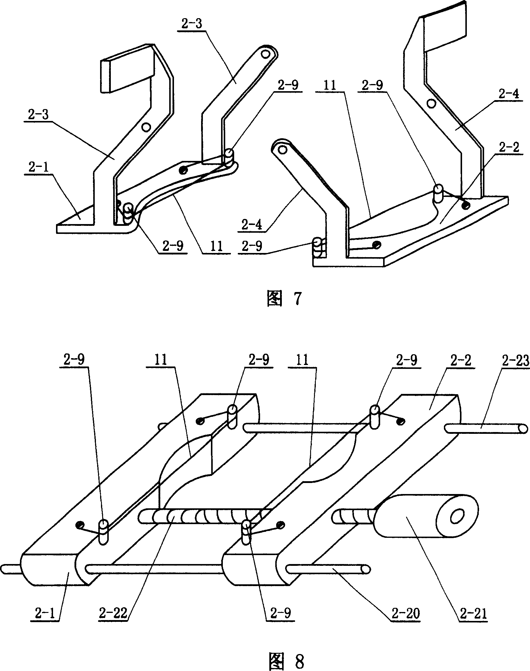
[0007] Specific Embodiment Three: The present embodiment will be specifically described below with reference to FIG. 8 . The difference between this embodiment and Embodiment 1 is that the wire cutting mechanism 2 consists of a left translation plate 2-1, a right translation plate 2-2, a first light bar 2-20, a second light bar 2-23, Drive motor 2-21, lead screw 2-22 and four heat-insulating insulation columns 2-9 are formed, and the two halves of lead screw 2-22 lengthwise direction have the screw thread of opposite direction respectively, and lead screw 2-22 is arranged on Between the first light rod 2-20 and the second light rod 2-23 and parallel to the first light rod 2-20 and the second light rod 2-23, the first light rod 2-20 is inserted into the left translation plate 2- 1 and one end of the right translation plate 2-2 provide a guide for parallel movement for the two, and the second light rod 2-23 inserts the other end of the left translation plate 2-1 and the right tr...
PUM
 Abstract
Description
Claims
Application Information
 - R&D
- Intellectual Property
- Life Sciences
- Materials
- Tech Scout
- Unparalleled Data Quality
- Higher Quality Content
- 60% Fewer Hallucinations
Browse by: Latest US Patents, China's latest patents, Technical Efficacy Thesaurus, Application Domain, Technology Topic, Popular Technical Reports.
© 2025 PatSnap. All rights reserved.Legal|Privacy policy|Modern Slavery Act Transparency Statement|Sitemap|About US| Contact US: help@patsnap.com


