Microcomputer controlled semi-automatic optical fibre circling machine

A microcomputer-controlled, winding machine technology, applied in the directions of light guides, optics, optical components, etc., can solve problems such as the inability to guarantee winding quality, and achieve the effects of human-computer interaction, low cost, and simple mechanical structure design.

Inactive Publication Date: 2007-08-08
BEIHANG UNIV
View PDF4 Cites 0 Cited by
  • Summary
  • Abstract
  • Description
  • Claims
  • Application Information

AI Technical Summary

Problems solved by technology

How to wind a high-quality fiber optic ring is very important to the development of fiber optic gyroscopes. There are many winding methods, and the quadrupole symmetrical winding

Method used


Image

  • Microcomputer controlled semi-automatic optical fibre circling machine
  • Microcomputer controlled semi-automatic optical fibre circling machine
  • Microcomputer controlled semi-automatic optical fibre circling machine

Examples


Embodiment Construction

[0031] The present invention will be further described in detail below with reference to the accompanying drawings.

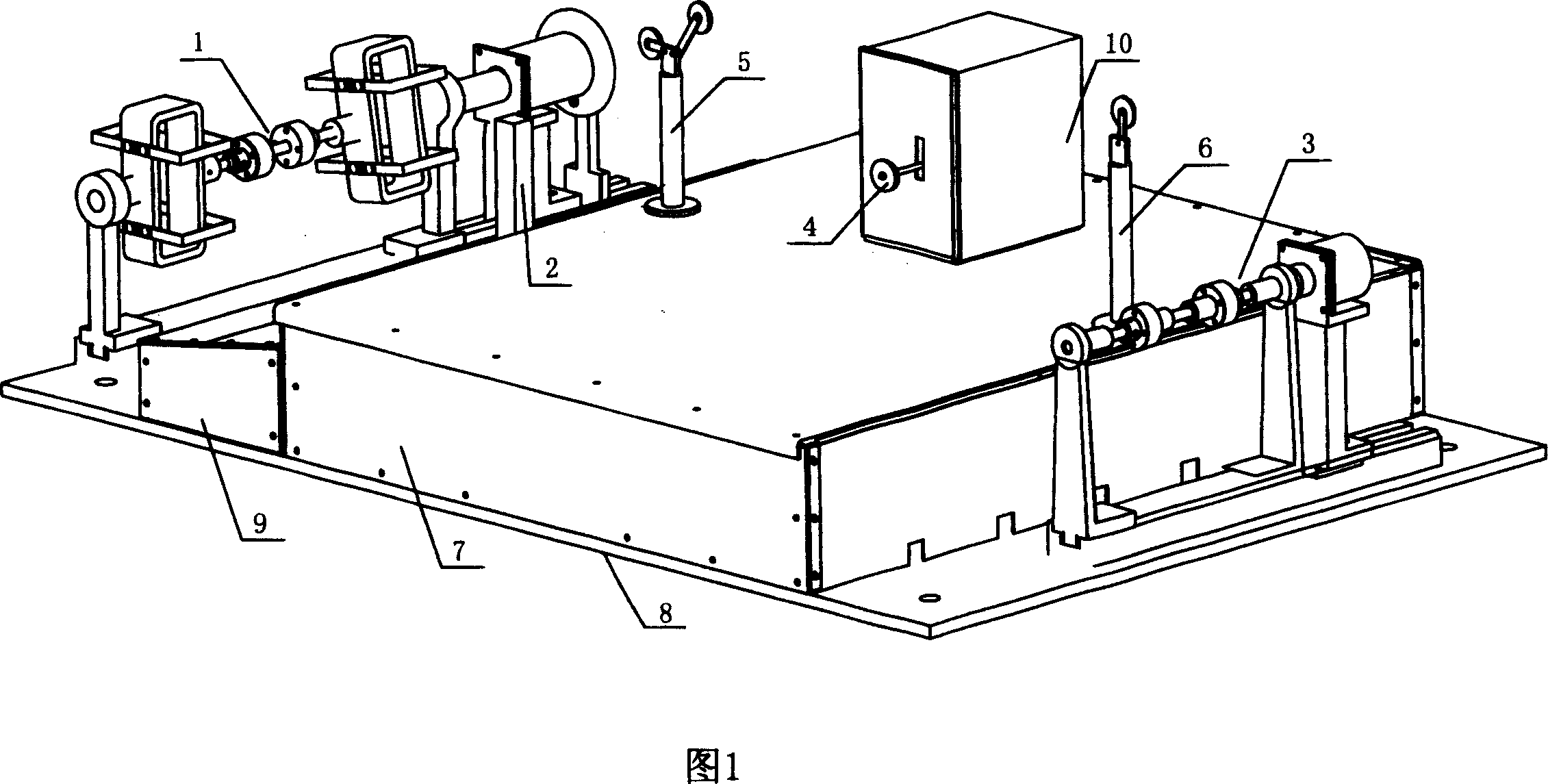
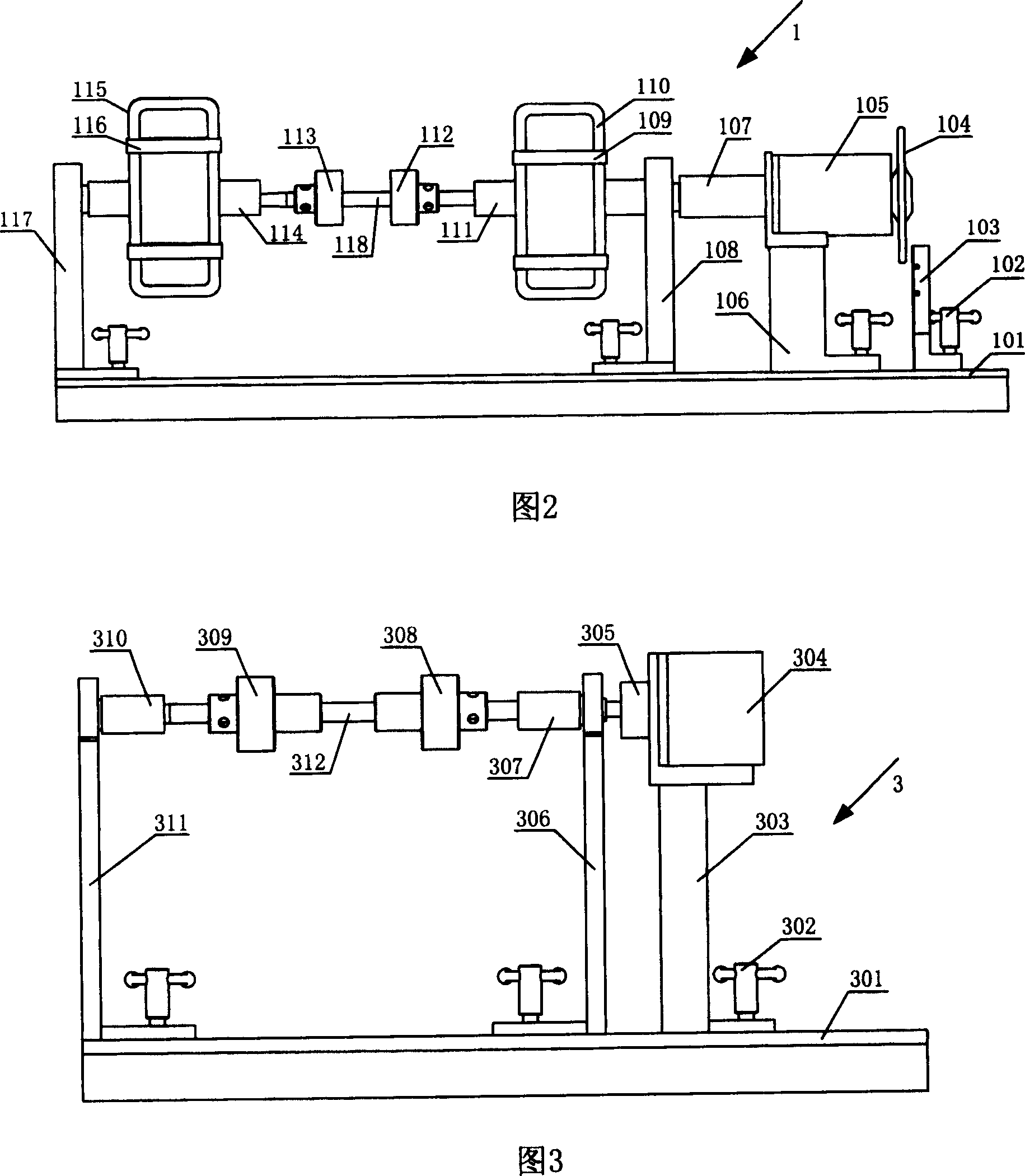
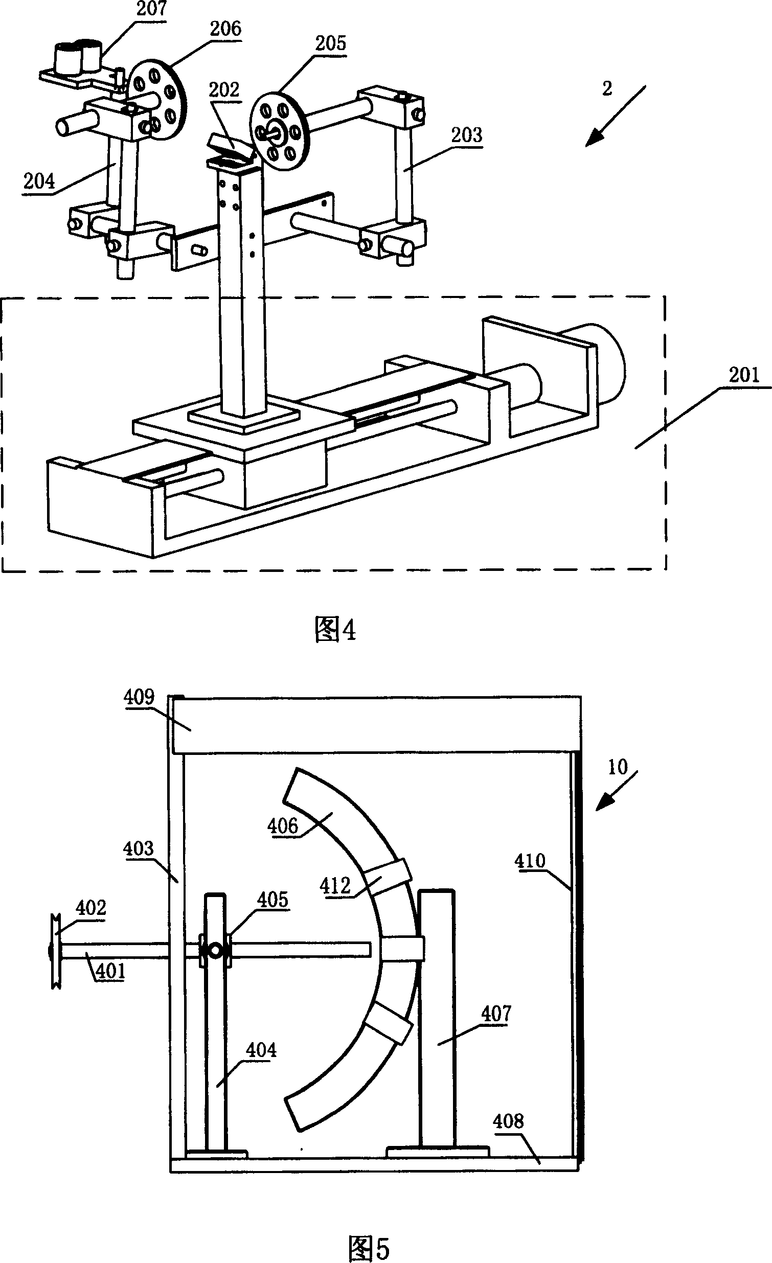
[0032] Please refer to Figures 1 to 5. The present invention is a microcomputer-controlled semi-automatic looping machine, including a PC, a program stored in the PC, and a looping machine. The looping machine is composed of a fiber supply mechanism 3, Fiber arranging mechanism 2, fiber collecting mechanism 1, tension control mechanism 4, chassis 8, box body 7 and winding electrical control system. In order to facilitate smooth fiber winding, a magnetic bracket can also be fixed on box body 7. The position is on the same axis as the tension control dancer 402 of the tension control mechanism 4 . The fiber supply mechanism 3, the fiber discharge mechanism 2, and the fiber collection mechanism 1 are installed on the chassis 8, and the tension control mechanism 4 is installed in the tension control box 10. The tension control box 10 is fixed on the box body 7 thro...


PUM


Abstract

The invention discloses a microprocessor controlled semi-automatic coiling machine, including PC machine, control program stored in the PC and coiling machine. Where the coiling machine is connected with the PC machine by the interface of the electric control system of the circling machine; the coiling machine is composed of fiber feeding mechanism, fiber arranging mechanism, fiber collecting mechanism, tension control mechanism and electric control system, where the fiber feeding, arranging and collecting mechanisms are installed on the underframe in sequence, the tension control mechanism is installed in a tension control box whose base board is installed on the box, which is installed on the underframe and the electric control system is installed in the box; the coiling machine can coil a Phi0.16-Phi0.25mm optical fiber, arrange lines at intervals of 1-60 mm, control tension at 0-15g and implement four-stage coiling method and complete coiling fiber and coating glue, synchronously.

Description

technical field [0001] The invention relates to a winding device applied to an optical fiber in an optical fiber gyro, in particular to a microcomputer-controlled semi-automatic winding machine. Background technique [0002] The fiber optic gyroscope was born in 1976. It is a new type of sensor that uses optical fiber sensing technology to measure the inertial rotation rate in space. It has developed into a new mainstream instrument with epoch-making characteristics in the field of inertial technology. Compared with the laser gyroscope, it has higher precision, low cost, small size and light weight. The application prospect of fiber optic gyroscope is very broad. It is not only used for the navigation of aircraft and ships, missile guidance, and high-precision position control of spacecraft, but also for the guidance of luxury cars, as well as robots and automatic control systems, etc. . [0003] The optical fiber ring is the sensing core of the fiber optic gyroscope, and ...

Claims


Application Information

Patent Timeline
IPC IPC(8): B65H59/38B65H54/02G02B6/00G01C19/58
Inventor 孟照魁张春熹史洁琴张朝阳
Owner BEIHANG UNIV
Why Eureka
Try Eureka