Roller for continuous measuring stress distribution applied on strip

A technology for stress distribution and measuring rollers, applied in tension measurement, measuring device, electromagnetic measuring device, etc., can solve the problems of long time, complicated operation and expensive removal of guide rollers

Inactive Publication Date: 2002-04-03
PRIMETALS TECH FRANCE
View PDF2 Cites 15 Cited by
  • Summary
  • Abstract
  • Description
  • Claims
  • Application Information

AI Technical Summary

Problems solved by technology

Even if we use the already mentioned assembly on movable rods proposed in EP 0.270.442, this operation is complicated and expensive, because it usually takes a considerable time to remove the guide rollers, which leads to discontinued

Method used


Image

  • Roller for continuous measuring stress distribution applied on strip
  • Roller for continuous measuring stress distribution applied on strip
  • Roller for continuous measuring stress distribution applied on strip

Examples


Embodiment Construction

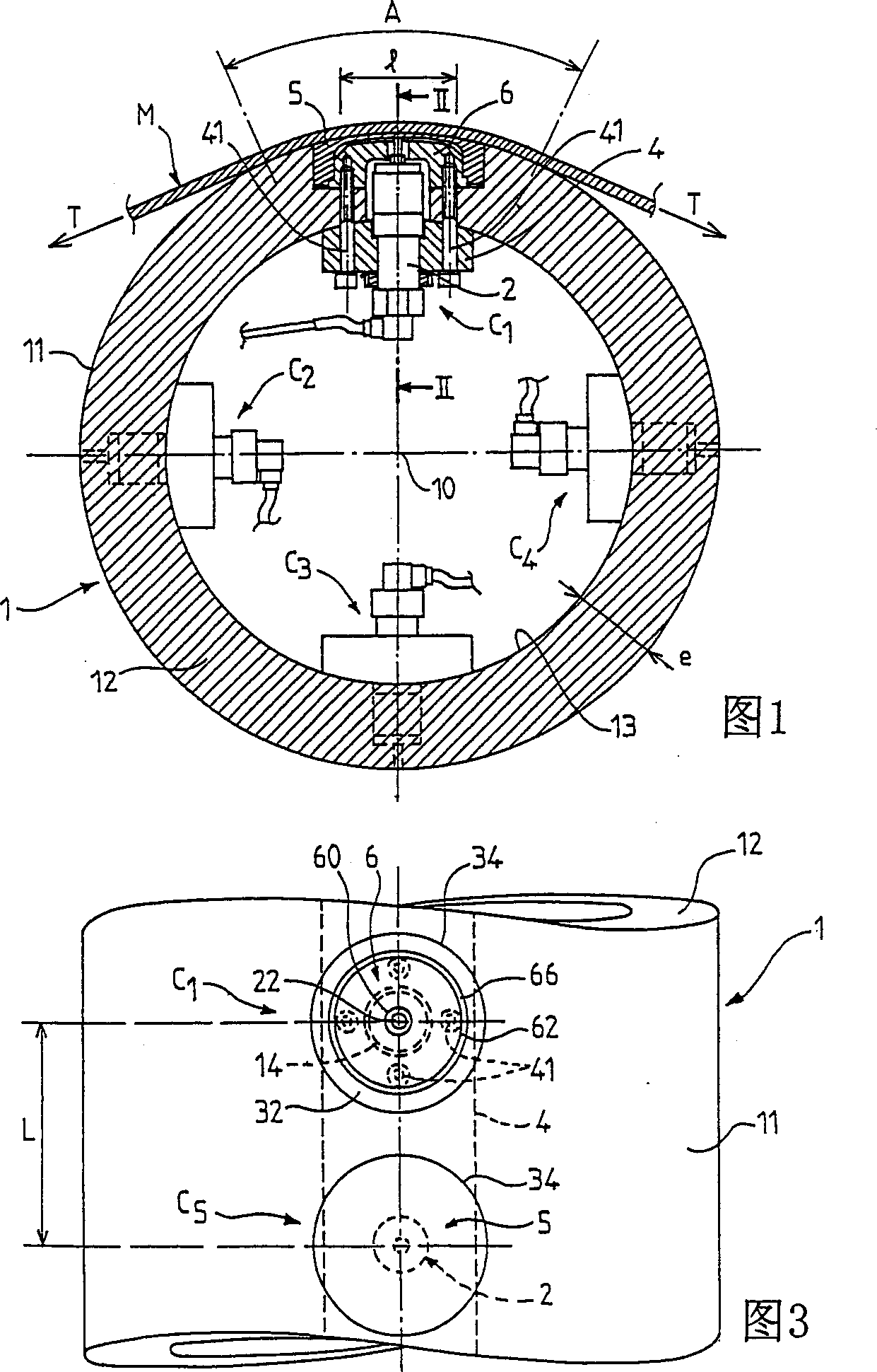
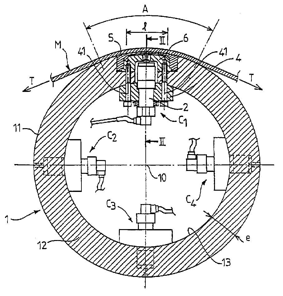
[0041] Figure 1 shows a cross-sectional view of a flatness measuring roll 1, which generally consists of a metal strip (M) running longitudinally perpendicular to the axis of rotation 10 of the roll and wound around the roll The guide rollers on the triangular sector constitute.

[0042] Said strip (M) maintains a tensile stress and therefore acts on the outer surface of the roller 1 under a pressure given by the following formula:

[0043] (2)p=T / R

[0044] where (T) is the tensile stress load per unit bandwidth and (R) is the radius of the outer surface of the roll.

[0045] The guide rollers according to the invention are of the type with displacement sensors as described in the European patent EP-0.028.191 of the same company. It is therefore equipped with several sensors spaced laterally at specific angles from one another. As described in the aforementioned patent EP-0.028.191, the different sensors are advantageously distributed on a helical curve wound on the outer ...


PUM


Abstract

The invention relates to a roll (1) for measuring the flatness of a band (M) comprising a tubular body (12) with a cylindrical external face (11) and a number of sensors each consisting of a feeler (2) mounted in a housing (3) provided in a recess in the thickness of the tubular body (12) and closed by a protection wall (50) whose deformations are measured by the feeler (2). According to the invention, each housing (3) is closed by a hollow piece in the shape of a lid (5) comprising a bottom made of an elastically deformable thin wall (50) and a peripheral part in the form of a bushing (53) encased without any clearance in the housing (3) and forming an embedding foot for the thin wall (50).

Description

technical field [0001] The invention relates to a measuring roll for continuous measurement of the stress distribution applied to a strip, in particular for detecting flatness defects of metal strips. Background technique [0002] When rolling metal strips and especially cold-rolled sheets, flatness defects arise which are caused in particular by slight variations across the width of the strip during elongation by rolling. [0003] The resulting flatness defect can be corrected while acting on the rolling conditions of the clamping pressure applied between the work rolls, especially in the transverse direction. [0004] In modern rolling mills, in practice, the load distribution can be acted on locally, for example by thermal action, by zone injection systems or by mechanical action, while bending loads are applied at the ends of the rolls. It is also possible to use a support roller comprising a deformable outer layer rotatably mounted on a fixed shaft and resting on said ...

Claims


Application Information

Patent Timeline
Patent Type & Authority Applications(China)
IPC IPC(8): G01B5/28B21B38/02G01B7/287G01B7/34G01L5/04
CPCG01L5/045G01B7/345G01B7/287B21B38/02G01B5/28
Inventor 雷米·佩雷农让-保罗·富尔
Owner PRIMETALS TECH FRANCE
Why Eureka
Try Eureka