

Display device of electronic apparatus provided with solar cell
A technology for solar cells and electronic devices, which is applied to mechanical devices, batteries, electrochemical generators and other directions indicated by time, can solve the problems of the depth of the display panel pattern and the unsatisfactory three-dimensional effect, and achieve excellent three-dimensional effect and pattern. Enrich and increase the effect of the design
- Summary
- Abstract
- Description
- Claims
- Application Information
AI Technical Summary
Problems solved by technology
Method used
Image

Examples
no. 1 example
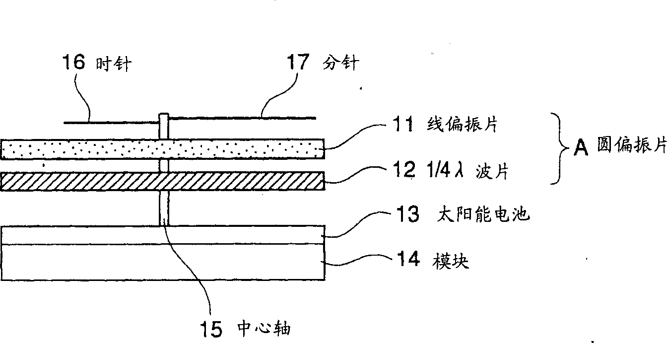
[0072] The description of the function of circular polarization has been completed, and the following will refer to figure 1 The first embodiment will be described in detail.
[0073] as figure 1 As shown, a watch with a solar cell includes a solar cell 13 electrically connected to a module 14 , and a minute hand 17 and an hour hand 16 fixed to a central axis 15 . Between the pointers 16 and 17 and the solar cell 13, a circular polarizing plate A including a linear polarizing plate 11 and a 1 / 4λ wave plate 12 is provided.
[0074] With this structure, the solar cell element dividing line of the solar cell 13 cannot be seen through the circular polarizing plate composed of the linear polarizing plate 11 and the 1 / 4λ wave plate 12 . In addition, since reflected light is eliminated, the color of the surface of the linear polarizing plate 11 is deepened, so that a high-quality feeling of the article can be obtained.
[0075] In this embodiment, marks such as numbers are direc...
no. 2 example
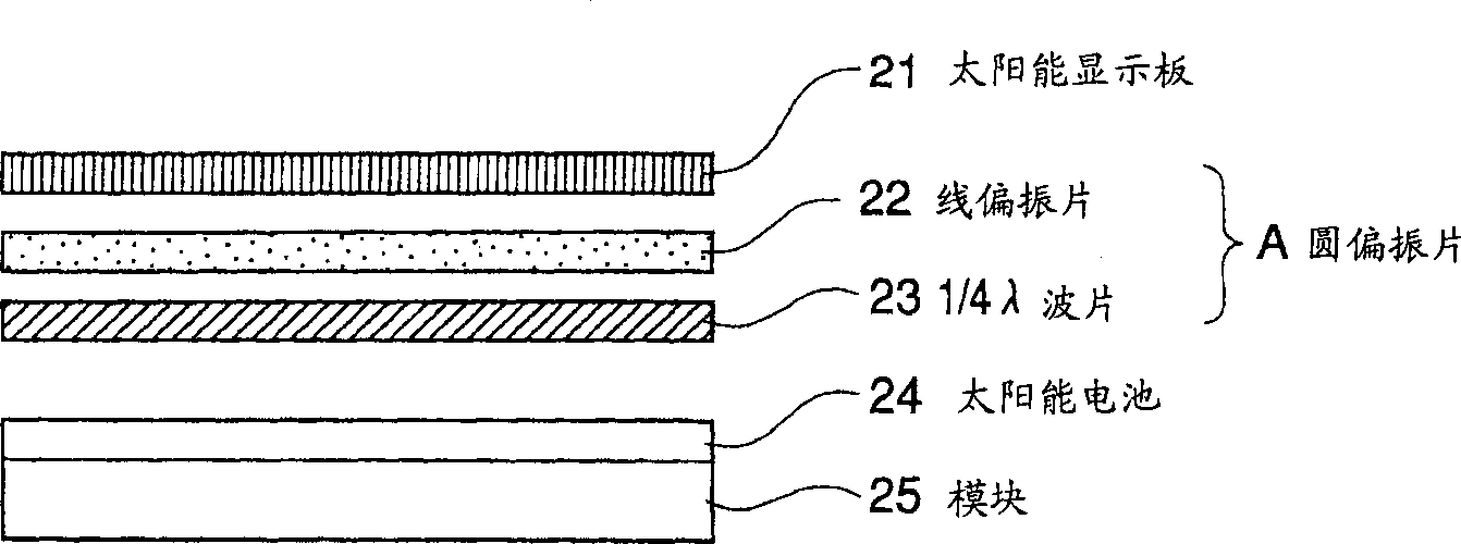
[0079] as figure 2 As shown, a circular polarizing plate A including a linear polarizing plate 22 and a 1 / 4 lambda wave plate 23 is arranged between the solar cell 24 and the solar display panel 21 with light transmittance.
[0080] Therefore, the dividing line of the solar cell element of the solar cell 24 cannot be seen through the solar display panel 21 , thereby increasing the variation in the design of the solar display panel 21 . In addition, the color of the solar display panel 21 is darkened so that a high-quality feeling of the item can be obtained.
[0081] In the work of assembling the watch, at first, the module 25 is prepared, and the shapes of the solar display panel 21, the solar cell 24, the linear polarizing plate 22, and the 1 / 4λ wave plate 23 are simultaneously processed by die-casting or the like, so as to figure 2 The structure shown superimposes them in a case (not shown) to obtain the finished watch. Therefore, preferably, the circular polarizing pla...
no. 3 example
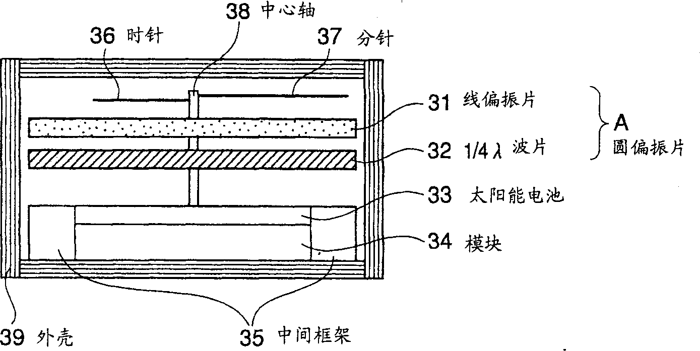
[0083] In this example, image 3 The structure of a watch is shown, in which a module 34 with a solar cell 33 is fixed via an intermediate frame 35 into a case 39 .
[0084] A circular polarizing plate A composed of a linear polarizing plate 31 and a 1 / 4 lambda wave plate 32 is provided on the intermediate frame 35 between the minute hand 37 and the hour hand 36 fixed on the central axis 38 and the solar cell 33 .
[0085] With this structure, the boundary line between the solar cell 33 and the intermediate frame 35, the sprue mark produced by the injection molding of the intermediate frame 35, and also the solar cell element dividing line of the solar cell 33 pass through the line formed by the linear polarizing plates 31 and 1. The circular polarizing plate A composed of the / 4λ wave plate 32 cannot be seen.
[0086] In addition, preferably, the circular polarizing plate A should be arranged to cover the solar cell 33 and the intermediate frame 35, as shown in the figure. ...
PUM
 Abstract
Description
Claims
Application Information