No-delay zero-crossing trigger circuit with thuristor throw-in and throw-off capacitor

A thyristor switching, capacitor technology, applied in reactive power compensation, reactive power adjustment/elimination/compensation and other directions, can solve the problems of reduced power consumption, poor triggering characteristics of thyristors, and poor triggering characteristics of trigger circuits

Inactive Publication Date: 2002-04-17
锦州华瑞新电力自动化有限公司
View PDF0 Cites 2 Cited by
  • Summary
  • Abstract
  • Description
  • Claims
  • Application Information

AI Technical Summary

Problems solved by technology

[0003] The present invention is to solve the problem that the triggering characteristics of the existing thyristor switching capacitor trigger circuit are not good, which causes the thyristor conduction voltage to be too high, and provides a triggering characteristic that does not affect the trigger voltage of the thyristor itself and the inrush current of the switching capacitor. Low, Thyristor-switched capacitors without time-delay zero-crossing trigger circuit to ensure the safe and reliable operation of reactive power compensation devices composed of capacitors and thyristors and other components
[0005] Since the thyristor switching capacitor has no delay an

Method used


Image

  • No-delay zero-crossing trigger circuit with thuristor throw-in and throw-off capacitor
  • No-delay zero-crossing trigger circuit with thuristor throw-in and throw-off capacitor

Examples


Embodiment Construction

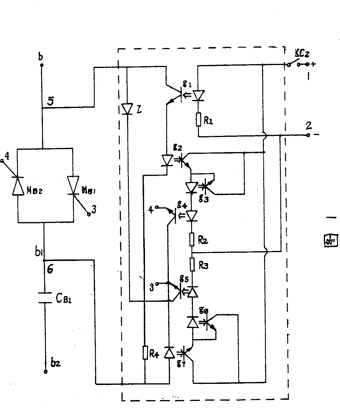
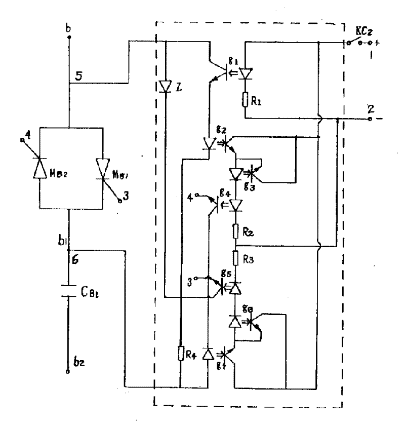
[0007] Such as figure 1 As shown in the dotted line box, the thyristor switched capacitor zero-crossing trigger circuit without delay is composed of the main control optocoupler g1, the positive and negative half-cycle conduction optocouplers g2 and g7, two holding optocouplers g3 and g6, and the negative and positive half-cycle trigger light Couplers g4 and g5 and current limiting resistors R1~R4, the input terminal of the main control optocoupler g1 and the current limiting resistor R1 are connected in series between the input terminals 1 and 2 of the DC power supply, and the output of the main control optocoupler g1 terminal, positive half-cycle conduction optocoupler g2 input terminal and current limiting resistor R4 are connected in series between the AC power input terminals 5 and 6 of the thyristor switching capacitor non-delay zero-crossing trigger circuit, and between the DC power input terminals 1 and 2 The positive half-cycle conduction optocoupler g2 output end, th...


PUM


Abstract

The invention relates to thyristor throw-in and throw-off capacitor no-delay zero-crossing trigger circuit, that provides features of good trigging characteristic, lower power consumption and withoutinfluencing the trigging voltage of thyristor itself. The photo-coupler input end of main control and a limiting resistor are connected in series and across input ends of DC source. The photo-coupleroutput end of main control is connected to the photo-coupler input end that turns on at positive half cycle as well as a limiting resistor in series, then the input end of AC source is out. Main control loop is composed of dc power source, the photo-coupler output and input end. Two AC input ends are connected to diode and photo-coupler output end that turns on at positive half cycle as well as aphoto-coupler input end and photo-coupler output end that turns on at negative half cycle, then the triggering end of the invented circuit is led out.

Description

technical field [0001] The invention relates to a trigger circuit, in particular to a thyristor switched capacitor zero-crossing trigger circuit without time delay applicable in a power grid. Background technique [0002] At present, the working circuits used in thyristor zero-crossing triggering in our country are divided voltage sampling, and it is judged that when the sampling voltage is less than the set value, the pulse circuit is given. Because the sampling voltage of this circuit is not the real power supply voltage, and the parameters of the components in the circuit are affected by temperature drift factors, the problem of high zero-crossing conduction voltage of the thyristor is caused. Usually it is 10 times of the trigger voltage of the tube conduction, and some even reach 30 times. It seriously affects the use characteristics of the thyristor, especially in the automatic switching circuit of the capacitor, which may generate a large inrush current and a transit...

Claims


Application Information

Patent Timeline
IPC IPC(8): H02J3/18
CPCY02E40/30
Inventor 张文会李春和哲学强
Owner 锦州华瑞新电力自动化有限公司
Why Eureka
Try Eureka