
Distributed type emergency reaction control system

A reaction control system and distributed technology, applied in memory systems, program control design, program control devices, etc., can solve problems such as inconvenience, single alarm information processing, and immediacy is not guaranteed.

Inactive Publication Date: 2002-05-15
上海光华如新信息科技股份有限公司
View PDF0 Cites 5 Cited by
  • Summary
  • Abstract
  • Description
  • Claims
  • Application Information

AI Technical Summary

Problems solved by technology

[0005] In the past computer security system, the problems encountered by the servers in the system can only be responded to individually, or can only be checked but not managed. This is very inconvenient for a computer network where the servers are distributed in multiple places. Not only does it require a large number of Human resources, consistency is not guaranteed, and the processing of alarm information is also very simple, either through the alarm box or through the system log, and the immediacy is not guaranteed

Method used


Image

  • Distributed type emergency reaction control system
  • Distributed type emergency reaction control system
  • Distributed type emergency reaction control system

Examples


specific Embodiment approach

[0078] In order to better understand the technical solution of the present invention, a further detailed description will be made below in conjunction with the accompanying drawings and embodiments.

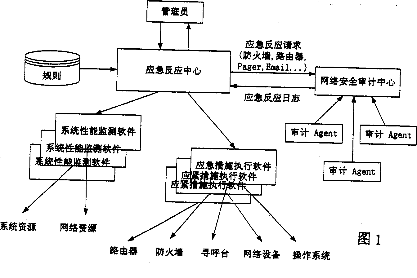
[0079] Fig. 1 is a system structure diagram of the present invention.

[0080] Figure 1 describes the structure of the actual operating system of the present invention and the connection relationship between modules.

[0081] The control system is mainly composed of an emergency response center, a number of abnormal event collection agents, and a number of emergency measure execution software. The emergency response center is the part that the administrator can operate. It provides the administrator's user interface. All rule settings and emergency alarm actions are It is carried out here, closely connected with the emergency response center is a global rule base, the rules of the entire system are recorded here, and the rules of different agents are sent to each agent through a ...


PUM


Abstract

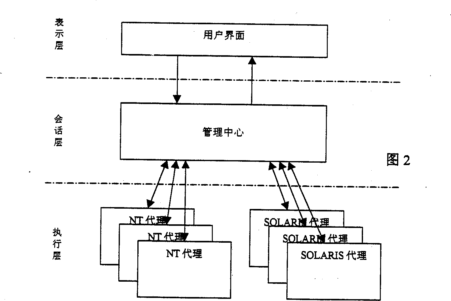
A distributed control system for emergency response is composed of three layers: user interface (presentation layer), management center (session layer) and agan (execute layer.). The information transferred between the center and agent follows coding protocol. The user interface receives the performance and alarm data transferred from the management center and sends the control information to agent process through the management center. The management center receives the performance data transferred from each agent, and then the data interpreted into the information of user readable is transferred to the user interface. According rules the management center writes alarm data to log and triggers a response. The invention can manage computers effectively, monitor working order of each computer and deals with violation with accuracy and automatically.

Description

Technical field: [0001] The invention relates to a distributed emergency response control system of a computer network, which is used for network monitoring and safety, and belongs to the field of computer technology. Background technique: [0002] With the rapid development of computer technology, communication technology, network technology, etc., computer systems have generally entered the stage of distributed network systems, and more and more manpower, material and financial resources are invested in this promising field. , after all, the distributed network system model has extremely obvious advantages (such as high performance, resource sharing, convenient communication, real-time control, risk dispersion, etc.) Therefore, more and more computer applications begin to adopt distributed design, and realize different functions through different computer devices to provide the best computing and service functions. [0003] But many existing distributed network systems ha...

Claims


Application Information

Patent Timeline
Patent Type & Authority Applications(China)
IPC IPC(8): G06F9/40G06F9/44G06F15/16
Inventor 张世永刘松鹏郭正跃
Owner 上海光华如新信息科技股份有限公司
Learn More