Voltage control apparatus for automotive electric generator

a voltage control and electric generator technology, applied in the direction of electric generator control, dynamo-electric converter control, control systems, etc., can solve the problem that the terminal voltage of the battery clue to the application of electrical loads may become large, and it is difficult for the rotational speed of the engine to follow the large drop in the terminal voltage of the battery, so as to achieve the effect of reliably suppressing the increase in the field curren

Inactive Publication Date: 2010-09-09
DENSO CORP
View PDF10 Cites 28 Cited by
  • Summary
  • Abstract
  • Description
  • Claims
  • Application Information

AI Technical Summary

Benefits of technology

[0020]With the above configuration, it is possible to more reliably suppress the increase in the field current by the voltage response control when the rotational spee

Problems solved by technology

As a result, a variation in the torque of an automotive electric generator, which is driven by the engine of a motor vehicle, may cause hunting of the engine to occur in some rotational speed region.
However, with the aging of an automotive battery that is charged by the generator, the drop in the terminal voltage of the battery clue to the application of an electrical load may become large.
Therefore, with the approach disclosed in Patent Document 1, it may be difficult for the rotational speed of the engine to follow the large drop in the terminal voltage of the battery.
As a result, the large drop in the terminal voltage of the battery may trigger hunting of the engine so that the rotational speed of the engine fluctuates and gradually converges on a target idle speed.
Consequently, the chargin

Method used


Image

  • Voltage control apparatus for automotive electric generator
  • Voltage control apparatus for automotive electric generator
  • Voltage control apparatus for automotive electric generator

Examples


Embodiment Construction

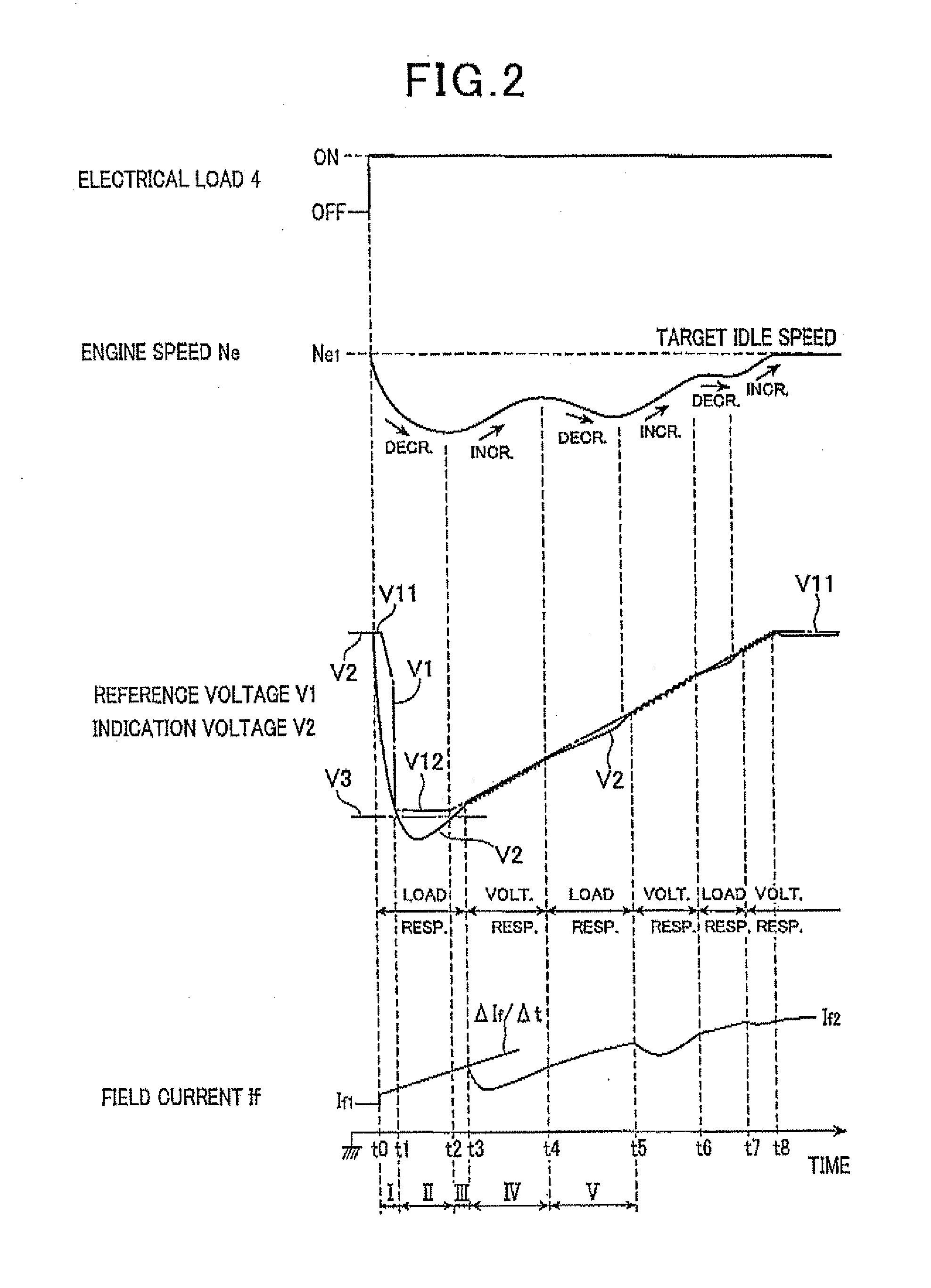
[0027]One preferred embodiment of the present invention will be described hereinafter with reference to FIGS. 1-2.

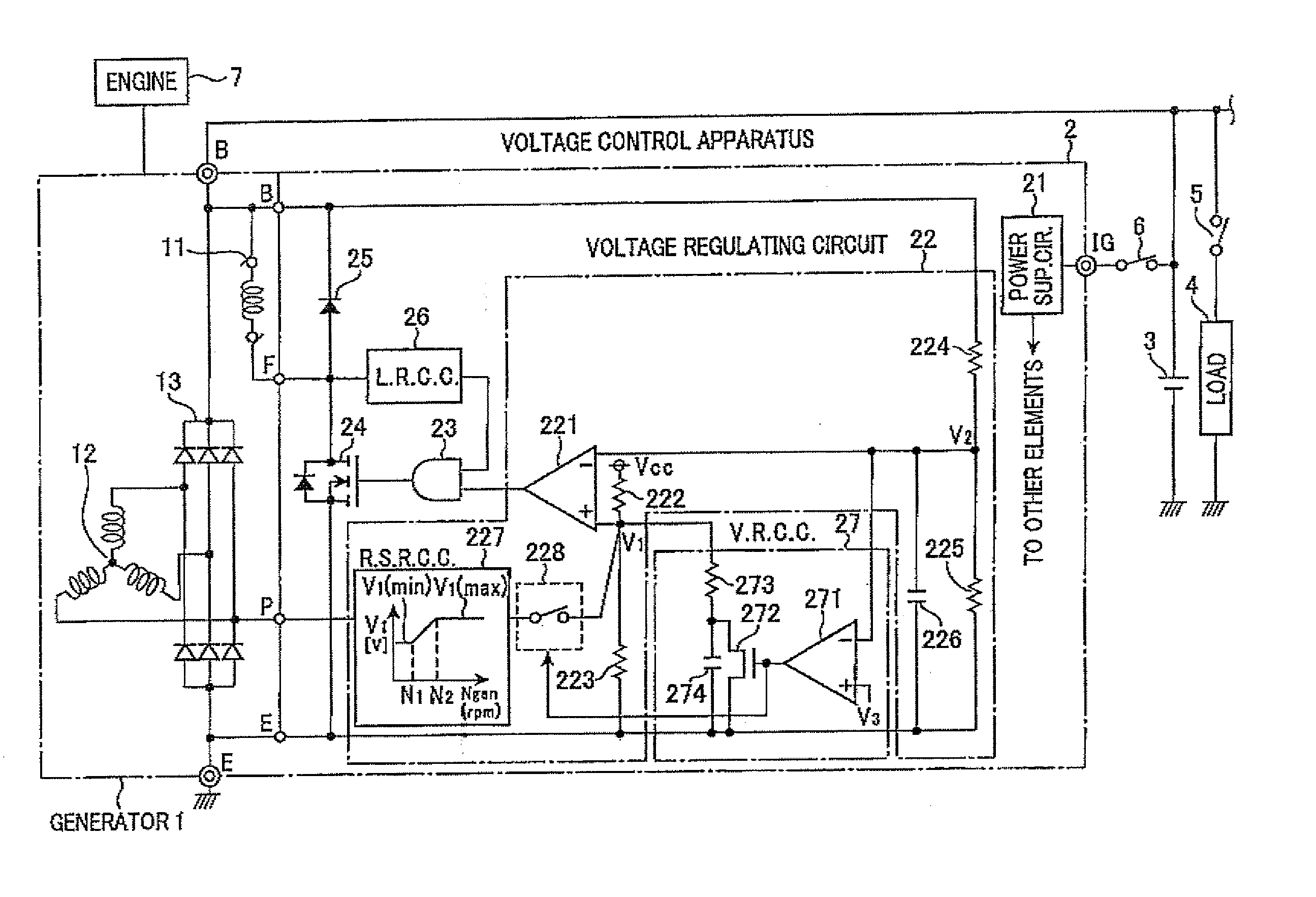
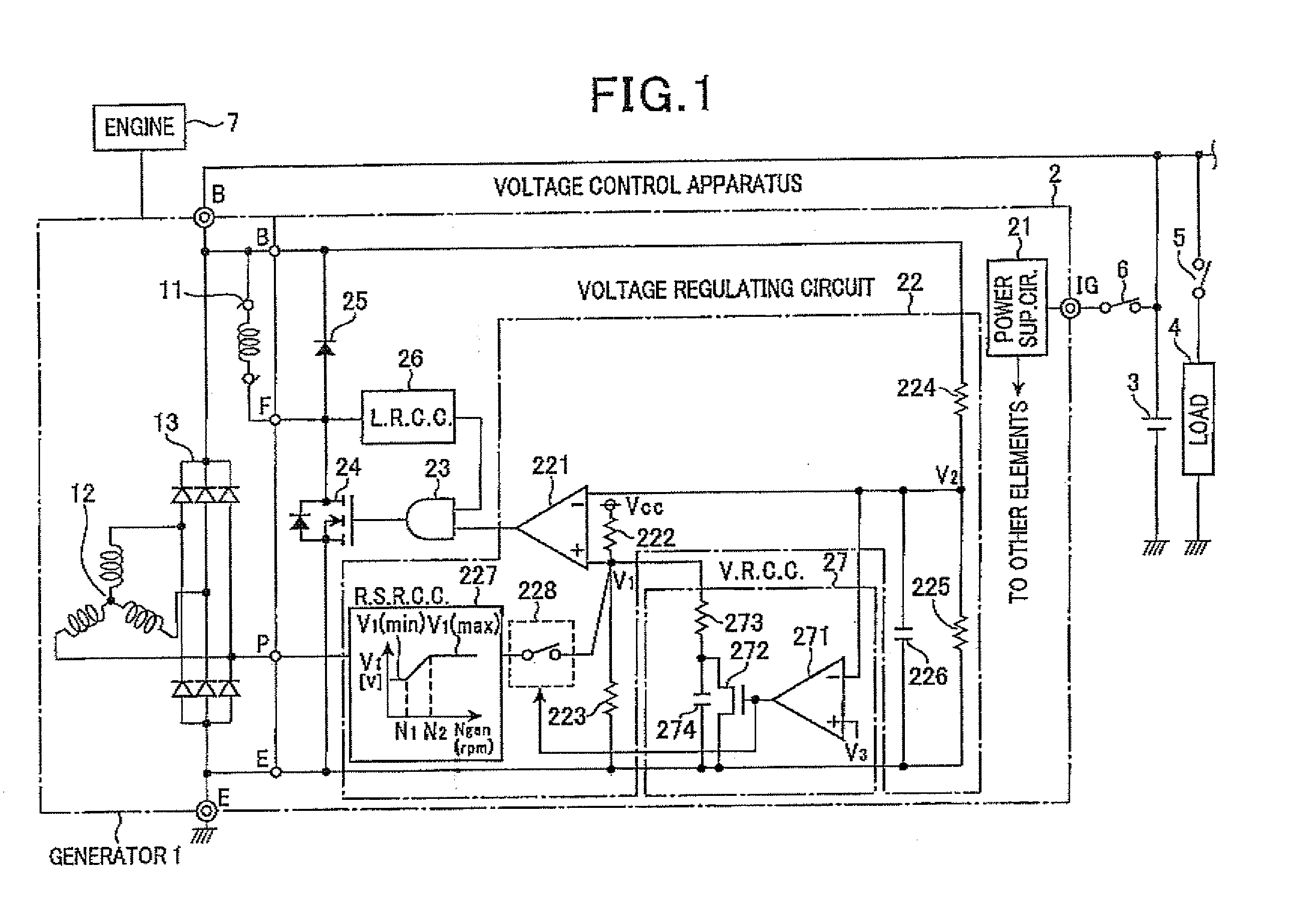
[0028]FIG. 1 shows the configuration of a voltage control apparatus 2 according to the preferred embodiment and its electrical connection with an automotive electric generator 1, a battery 3, and an electrical load (e.g., a headlight) 4.

[0029]As shown in FIG. 1, the voltage control apparatus 2 is electrically connected to the generator 1 to control the output voltage VB of the generator 1 at an output terminal (or battery terminal) B of the generator 1. The output terminal B is also electrically connected to the battery 3 and the electrical load 4.

[0030]The generator 1 includes a field winding 11, a three-phase stator winding 12, and a rectifier 13.

[0031]The field winding 11 is wound around a field pole (not shown) to form a rotor of the generator 1. The rotor creates a rotating magnetic field when field current is supplied to the field winding 11 during rotation of the ...


PUM


Abstract

A voltage control apparatus for an electric generator includes a load response controller and a voltage response controller. The electric generator includes a field winding and is driven by an engine of a motor vehicle. When the output voltage of the generator decreases below a threshold voltage upon the application of an electrical load, the rotational speed of the engine fluctuates to repeatedly increase and decrease until it is stabilized. During the time periods in which the rotational speed of the engine decreases, field current supplied to the field winding of the generator is gradually increased under a load response control performed by the load response controller. During the time periods in which the rotational speed of the engine increases, the field current is gradually increased under a voltage response control by the voltage response controller.

Description

CROSS-REFERENCE TO RELATED APPLICATION[0001]This application is based on and claims priority from. Japanese Patent Application No. 2009-50275, filed on Mar. 4, 2009, the content of which is hereby incorporated by reference in its entirety into this application.BACKGROUND OF THE INVENTION[0002]1. Technical Field of the Invention[0003]The present invention relates to voltage control apparatuses for controlling output voltages of electric generators that are used in motor vehicles such as passenger cars and trucks.[0004]2. Description of the Related Art[0005]In recent years, to reduce emissions from motor vehicles and improve the fuel economy of the same, both engine idle speed and engine friction have been lowered. As a result, a variation in the torque of an automotive electric generator, which is driven by the engine of a motor vehicle, may cause hunting of the engine to occur in some rotational speed region. Hereinafter, hunting of the engine denotes a phenomenon in which the rotat...

Claims


Application Information

Patent Timeline
IPC IPC(8): H02P9/48
CPCH02P9/305H02P2101/45H02P9/48
Inventor AOYAMA, TORU
Owner DENSO CORP
Why Eureka
Try Eureka