Automatic gain controller

a gain controller and automatic technology, applied in the direction of gain control, digital transmission, amplifier combination, etc., can solve the problems of signal modulation, in-band object signal variation, signal interruption of conventional automatic gain controller, etc., to achieve the effect of easy measurement of the object signal level

Active Publication Date: 2006-09-26
SAMSUNG ELECTRONICS CO LTD
View PDF10 Cites 27 Cited by
  • Summary
  • Abstract
  • Description
  • Claims
  • Application Information

AI Technical Summary

Benefits of technology

[0029]The automatic gain controller having the above structure can easily measure the ob...

Problems solved by technology

In a conventional automatic gain controller having a filter in a control loop, an output signal of the conventional automatic gain controller is often interrupted due to a delay of response characteristics thereof caused by a signal delay from the filter.
In addition, although above-described Japanese Patent Publication No. 3,086,060 can adjust a signal level at a front end of a filter by tracking variations of levels of out-of-band signals of the filter, if an automatic gain control for the amplifier installed at the front end of the filter is carried out with a high-speed response according to ...

Method used


Image

  • Automatic gain controller
  • Automatic gain controller
  • Automatic gain controller

Examples


embodiment 1

[0047

[0048]First, an automatic gain controller according to a first embodiment of the present invention will be described.

[0049]A. Structure

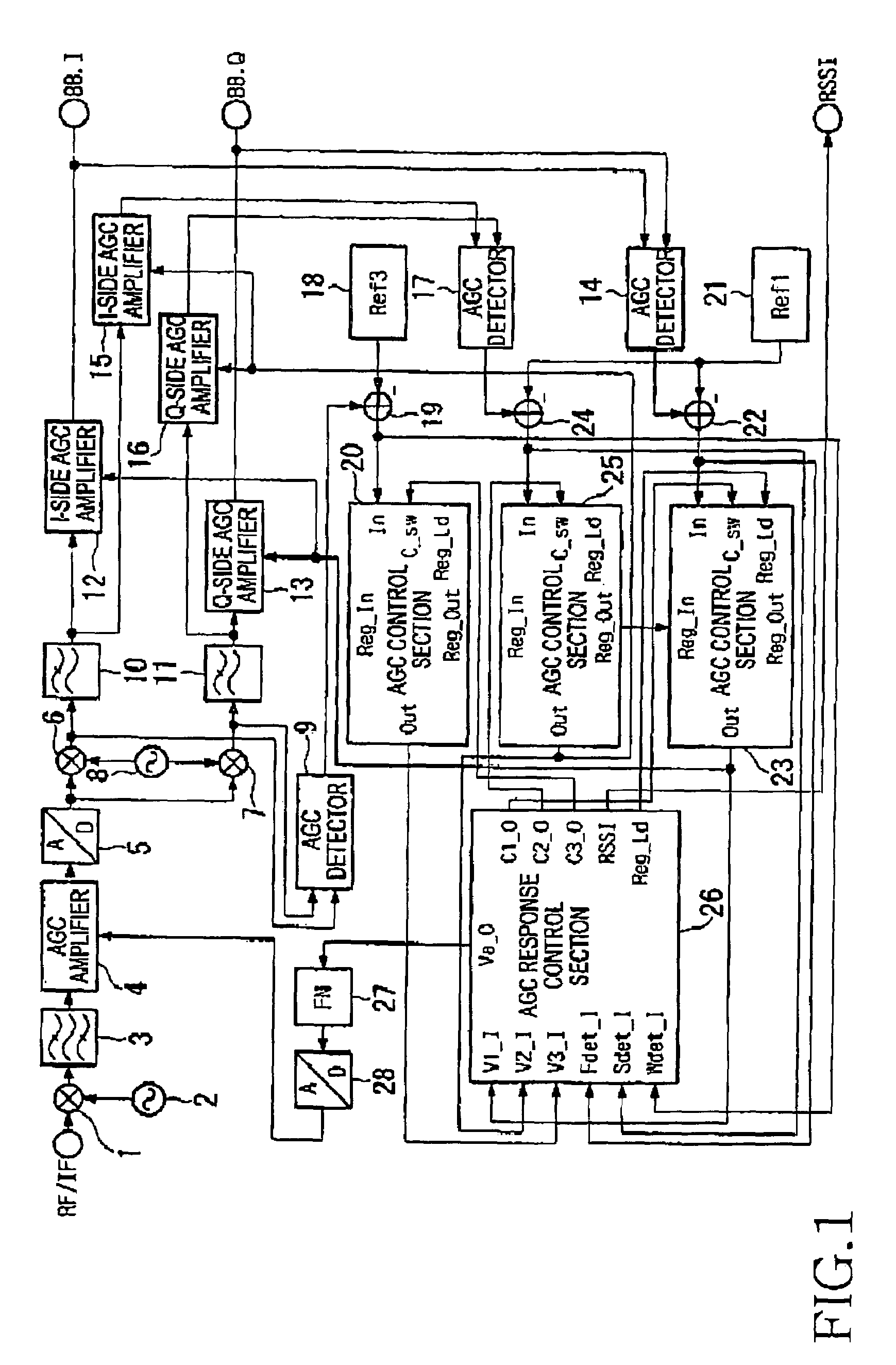
[0050]FIG. 1 is a block diagram showing a structure of a wireless apparatus having an automatic gain controller (AGC) according to the first embodiment of the present invention. Referring to FIG. 1, a signal inputted into a mixer 1 from an RF / IF terminal is converted into a signal having a low frequency (input IF frequency of A / D converter 5, which will be described later) in the mixer 1 by using a local signal having a first frequency, which is outputted from a local oscillator 2. Then, a signal having a predetermined frequency band is extracted from the signal outputted from the mixer by using a bandpass filter 3.

[0051]An AGC amplifier 4 is a variable gain amplifier for converting an output signal of the bandpass filter 3 into a signal having a constant level. The signal having the predetermined frequency band, which is converted into the sign...

embodiment 2

[0160

[0161]Hereinafter, an automatic gain controller according to a second embodiment of the present invention will be described.

[0162]A. Structure

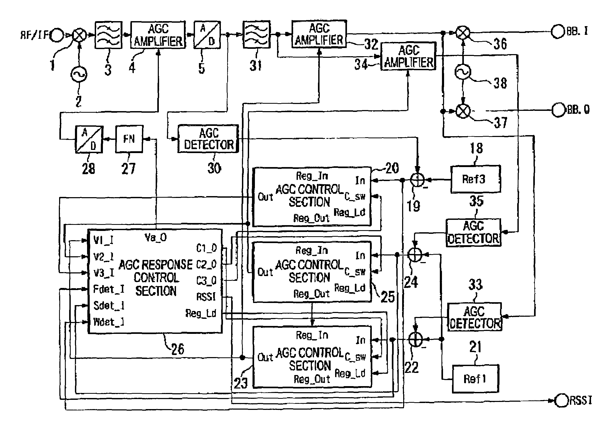
[0163]FIG. 9 is a block diagram showing a structure of a wireless apparatus having an automatic gain controller according to the second embodiment of the present invention. The automatic gain controller according to the second embodiment is different from the automatic gain controller according to the first embodiment in that the automatic gain controller according to the first embodiment performs an orthogonal detection for a signal received in the front end of the channel filter extracting the object signal, and the automatic gain controller according to the second embodiment performs the orthogonal detection for a signal received in the channel filter and for a signal received rearward of the AGC amplifier installed at the rear end of the channel filter, and the AGC detection is carried out with an absolute value of a real signal.

[0164...

embodiment 3

[0192

[0193]Hereinafter, an automatic gain controller according to a third embodiment of the present invention will be described.

[0194]A. Structure

[0195]FIG. 12 is a block diagram showing a structure of a wireless apparatus having the automatic gain controller according to the third embodiment of the present invention. The automatic gain controller according to the third embodiment is different from the automatic gain controller according to the second embodiment in that the automatic gain controller according to the second embodiment performs the gain control for the AGC amplifier, which is installed at the front end of the channel filter extracting the object signal, in an IF frequency band rearward of the mixer, and the automatic gain controller according to the third embodiment performs the gain control in an RF / IF frequency band forward of the mixer.

[0196]Therefore, the third embodiment will be described with regard to different parts between the automatic gain controller of the...


PUM


Abstract

Disclosed is an automatic gain controller capable of reducing signal saturation or signal distortion caused by out-of-band signals of a filter extracting an object signal or delay of a control signal and capable of precisely measuring a signal level in a filter band. An AGC response control section compares a level of control voltage (“V2_I terminal” signal) outputted from a first AGC control section and inputted into a “V2_I terminal” with a level of control voltage (“V3_I terminal” signal) outputted from a second AGC control section and inputted into a “V3_I terminal”. If the control voltage, which is the “V3_I terminal” signal, outputted from the second AGC control section is less than the control voltage, which is a “V2_I terminal” signal, outputted from the first AGC control section, the AGC response control section controls an AGC amplifier by using the control voltage outputted from the second AGC control section. If the control voltage, which is the “V3_I terminal” signal, outputted from the second AGC control section is greater than the control voltage, which is the “V2_I terminal” signal, outputted from the first AGC control section, the AGC response control section controls the AGC amplifier by using the control voltage outputted from the first AGC control section.

Description

PRIORITY[0001]This application claims priority to an application entitled “Automatic Gain Controller” filed in the Japanese Intellectual Property Office on Mar. 6, 2003 and assigned Ser. No. 59764 / 2003, the contents of which are hereby incorporated by reference.BACKGROUND OF THE INVENTION[0002]1. Field of the Invention[0003]The present invention relates to an automatic gain controller.[0004]2. Description of the Related Art[0005]In a conventional automatic gain controller having a filter in a control loop, an output signal of the conventional automatic gain controller is often interrupted due to a delay of response characteristics thereof caused by a signal delay from the filter. In order to solve the above problem, a method has been proposed, wherein if a signal level has a sudden variation, a control signal generator having a rapid time constant is utilized to create a control signal to cope with a delay of the control signal caused by the filter, and at the same time, control inf...

Claims


Application Information

Patent Timeline
IPC IPC(8): H04B1/06H04B7/00H03G3/20H03G3/30H04B1/16
CPCH03G3/3068H03G3/3036G08G1/005G08G1/09G08G1/07
Inventor KISHI, TAKAHIKO
Owner SAMSUNG ELECTRONICS CO LTD
Why Eureka
Try Eureka