Rotary buffering valve

A technology of rotary buffer and buffer valve, which is used in fluid pressure actuating devices, servo motor components, mechanical equipment, etc., can solve the problems of inconvenient installation and use, short service life, not concise and compact enough, etc. Easy to leak oil, compact structure

Inactive Publication Date: 2002-05-22
卢永松
View PDF0 Cites 42 Cited by
  • Summary
  • Abstract
  • Description
  • Claims
  • Application Information

AI Technical Summary

Problems solved by technology

However, in order to realize the above-mentioned control process on cranes, standard single-function hydraulic components are still mostly used and connected with complex piping. Therefore, it usually has a relatively large structure and is not concise and compact. Hydraulic components, so the pipelines connecting them are also relatively complicated, easy to leak oil, inconvenient to install and use, and relatively large in size, occupying a large space, so the failure rate is high, there are many safety hazards, and the service life is not long

Method used


Image

  • Rotary buffering valve
  • Rotary buffering valve
  • Rotary buffering valve

Examples


Embodiment Construction

[0020] Embodiments of the present invention will be further described in detail below with reference to the accompanying drawings.

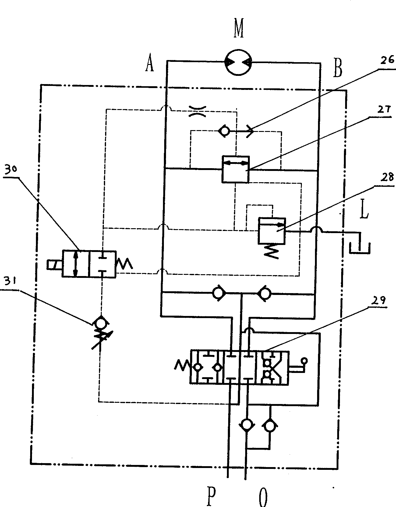
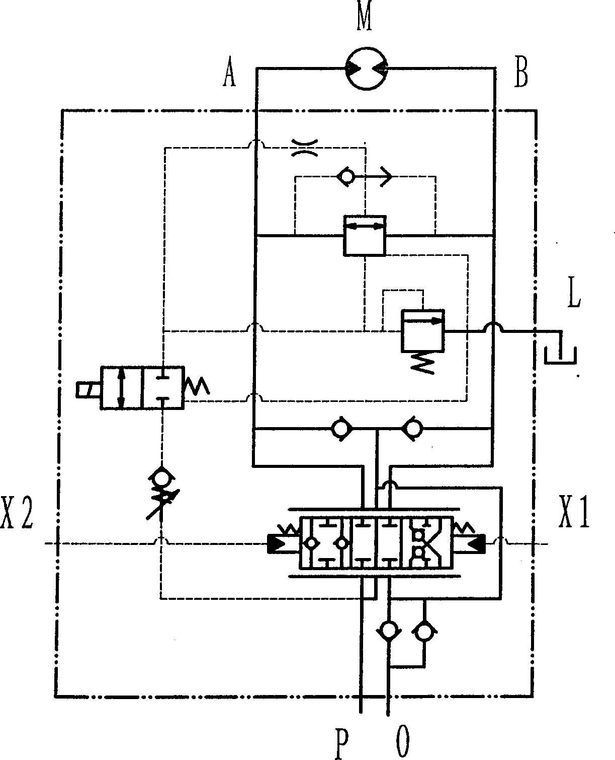
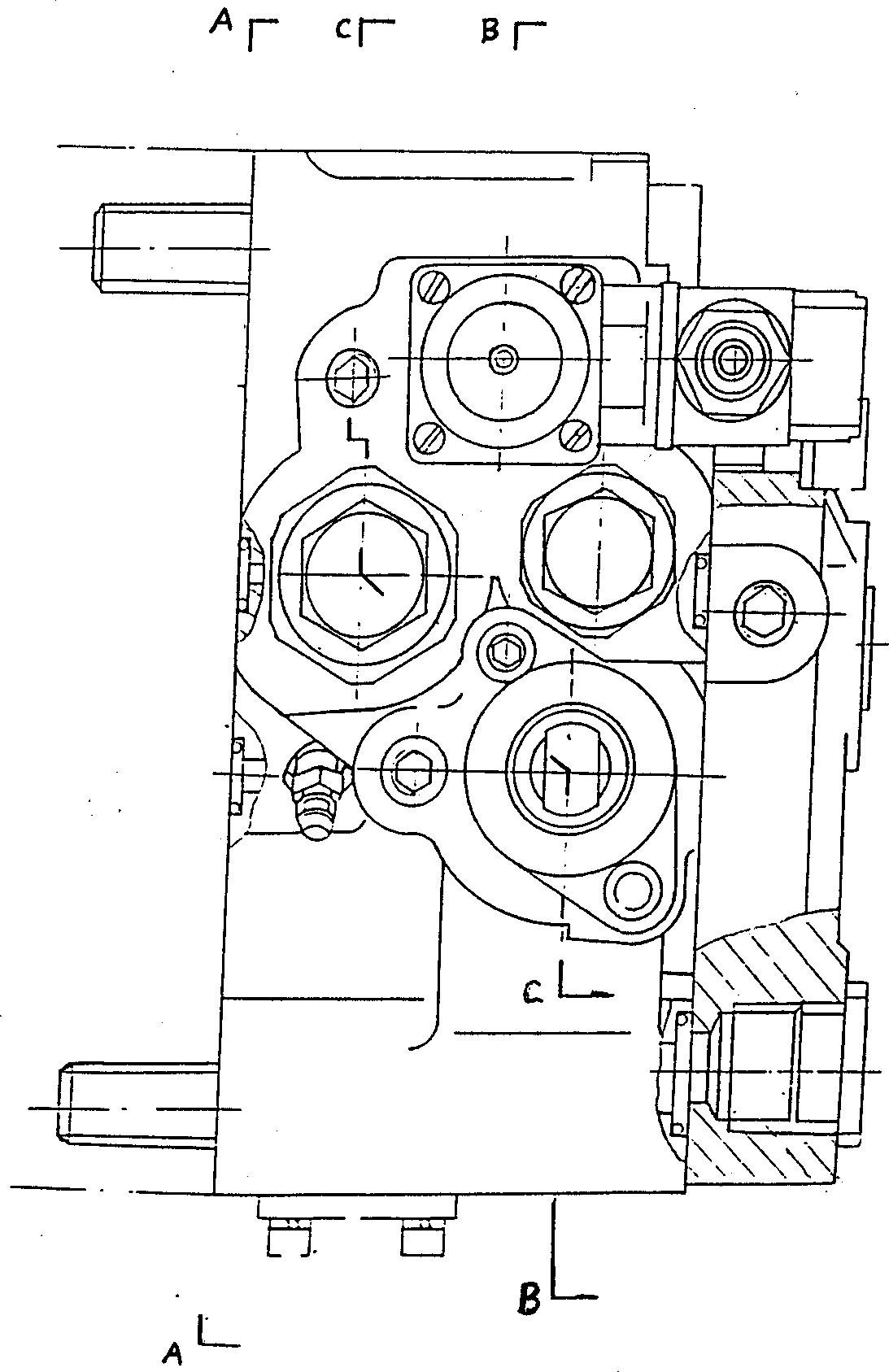
[0021] As shown in the figure, the main components of this type of rotary buffer valve are main valve body 1, damping 2, oil passage 3, solenoid valve core oil inlet 4, damping 5, buffer spool spring 6, pilot spool 7, pilot Spool spring 8, inner runner 9, selector valve steel ball 10, buffer spool 11, inner runner 12, solenoid spool spring 13, solenoid spool 14, adjustable back pressure spool 15, adjustable back pressure valve Core spring 16, electromagnet 17, built-in one-way spool spring 18, built-in one-way valve steel ball 19, oil return and replenishment one-way spool 20, oil return back pressure spool spring 21, oil return back pressure spool 22 , Inner flow channel 23, reversing valve stem 24, oil supply check valve core 25, selection valve 26, buffer valve 27, pilot valve 28, control valve 29, solenoid valve 30, adjustable back pressure v...


PUM


Abstract

The present invention relates to the turning buffer valve technology in crane, which is characterized by that in the main valve body through the installation of cavity, built-in channel and necessaryparts, the buffer valve, electromagnetic valve, adjustable backpressure valve, control valve and non-way valve are detachly combined in the main valve body to make it possess several functions of turning buffer valve in crane. Said invention possesses the advantages of reasonable compact structure, small volume and safe and convenient use, etc.

Description

technical field [0001] The invention relates to a slew buffer valve, in particular to the technical field of a slew buffer control valve used on the slewing mechanism of a 20-ton to 60-ton hydraulic truck crane. Background technique [0002] According to the actual use requirements, the traditional truck crane slewing mechanism generally has the following characteristics, that is, it can be quickly started and stopped quickly; Keep the lead weight of the steel cable and the arm frame rotate precisely and synchronously, etc., so that the crane can lift the goods safely, quickly and conveniently. However, in order to realize the above-mentioned control process on cranes, standard single-function hydraulic components are still mostly used and connected with complex piping. Therefore, it usually has a relatively large structure and is not concise and compact. Hydraulic components, so the pipelines connecting them are also relatively complicated, easy to leak oil, inconvenient t...

Claims


Application Information

Patent Timeline
Patent Type & Authority Applications(China)
IPC IPC(8): B66C23/88F15B13/02
Inventor 刘富良卢永松
Owner 卢永松
Why Eureka
Try Eureka