Screen printing equipment and method

A technology of screen printing and cover plate, applied in screen printing, screen printing machine, printing and other directions, can solve problems such as hardening printing quality

Inactive Publication Date: 2002-07-10
PANASONIC CORP
View PDF0 Cites 11 Cited by
  • Summary
  • Abstract
  • Description
  • Claims
  • Application Information

AI Technical Summary

Problems solved by technology

In the screen printing using the conventional sealed squeegee head in this way, prin

Method used


Image

  • Screen printing equipment and method
  • Screen printing equipment and method
  • Screen printing equipment and method

Examples


Embodiment 1

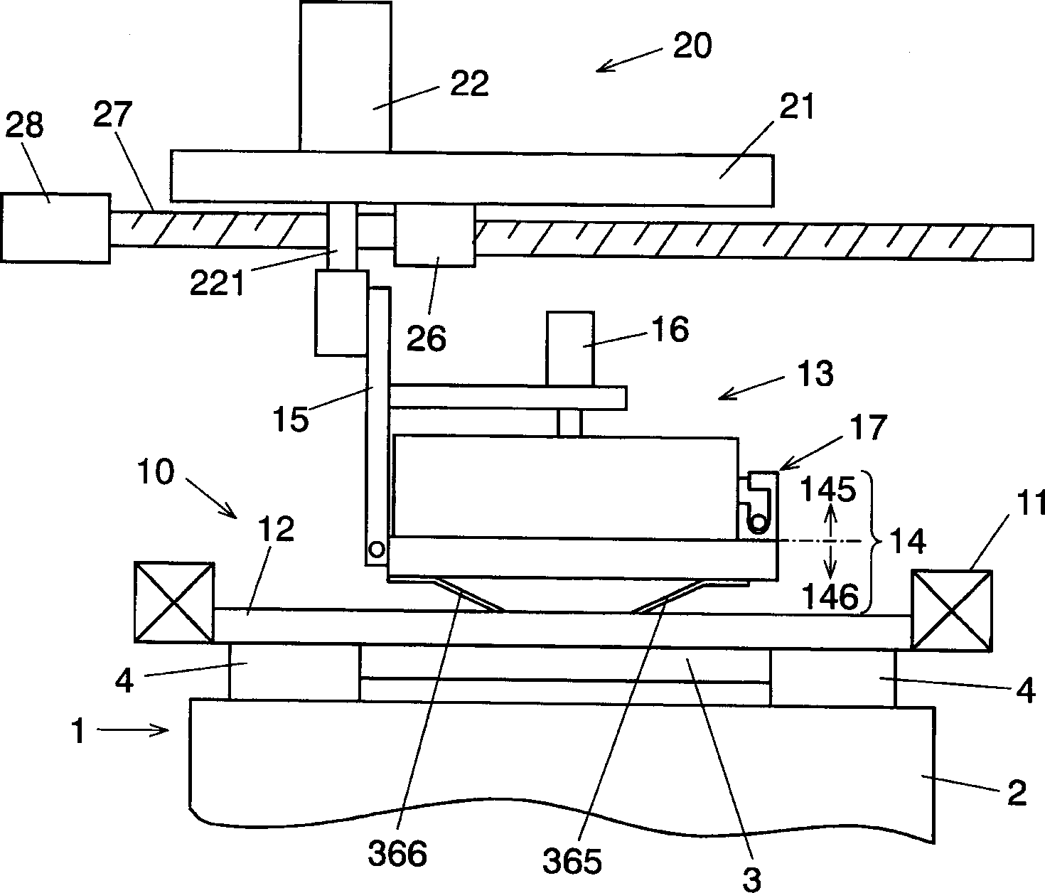
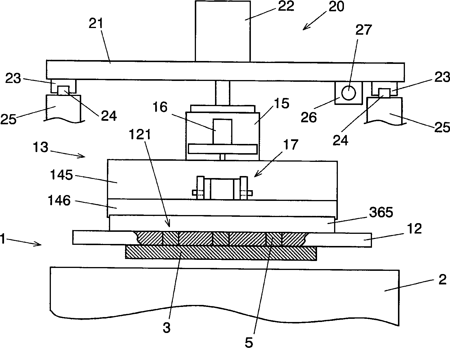
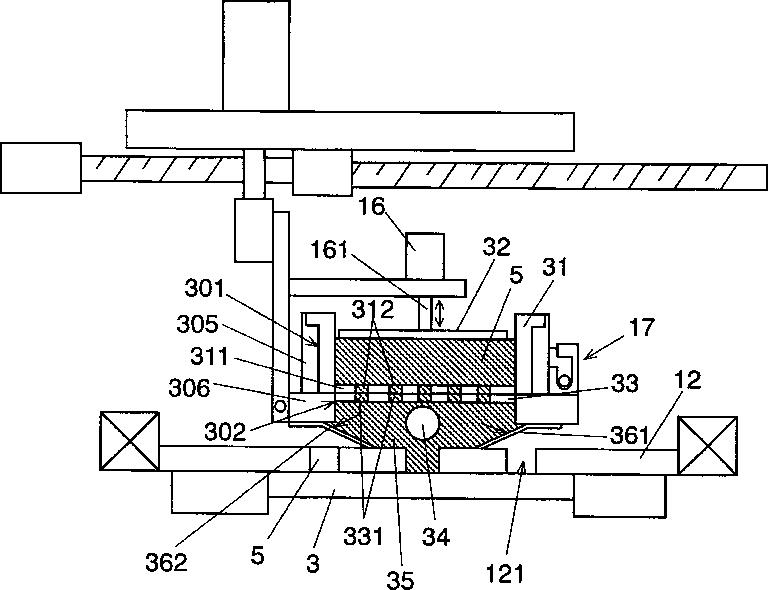
[0028] figure 1 is a front view of the screen printing device in Embodiment 1 of the present invention, figure 2 is a side view of the device, image 3 is a partial cross-sectional view of the device, Figure 4 , Figure 5A and Figure 5B yes figure 1 Partial cutaway view of the squeegee head in the screen printing setup shown. in Figure 5A It is a figure which assumes that there is no rectification part for explanation. Figure 6A and Figure 6B It is a partial sectional view of another squeegee head.

[0029] First, refer to figure 1 , figure 2 and image 3 The configuration of the screen printing device will be described. exist figure 1 and figure 2 Among them, the substrate positioning unit 1 is provided with a substrate support unit 2 on a moving table (not shown). The substrate 3 to be printed is held by the clamper 4 of the support part 2, and the position of the substrate 3 in the horizontal and vertical directions is determined by driving the moving...

Embodiment 2

[0054] Figure 7A It is a partial sectional view of the squeegee head of the screen printing device in Embodiment 2 of the present invention. Figure 7B is a partial perspective view of the squeegee head. This second embodiment is a screen printing apparatus in which the squeegee head 13 having the same structure as that shown in the above-mentioned embodiment 1 is provided with components different from those of the first embodiment in the flux storage portion 35 .

[0055] exist Figure 7A In the accommodating part 35, the spacer member 44 is arranged. Figure 7B The spacer member 44 shown in is a member that combines a plurality of partition plates 441 in the vertical direction into a lattice shape viewed from a plan view. When the solder paste 5 moves downward in the housing portion 35 , the solder paste 5 moves in the space between the partitions 441 . At this time, a considerable amount of solder in all solder paste volumes moves downward along the vicinity of the su...


PUM


Abstract

A screen printing apparatus. Cream solder stored in a squeegee head is pressurized by a pressurizing plate, and the squeegee head is slid on a mask plate, so that the cream solder is printed onto a substrate via pattern apertures. This is done by a screen printing apparatus, in which pressurized solder is accommodated, and the solder is brought into contact with a surface of the mask plate via an opening formed on a lower face of the cell. A rectifier is disposed in the cell for blocking the cream solder from flowing into a specific area just above the opening. This structure allows the solder to flow into the opening in a slant direction, and causes the solder to roll. This mechanism prevents the solder from being hardened due to staying stagnant just above the opening, and thus prevents defective printings.

Description

technical field [0001] The invention relates to a screen printing device and a screen printing method for printing flux such as solder paste and conductive flux on a substrate, and in particular relates to a squeegee head which is characterized in that it can maintain the fluidity of the flux and prevent the solder from being caused by the hardening of the flux. A screen printing device and a screen printing method for printing quality problems. Background technique [0002] In the electronic component mounting process, screen printing is used as a method of printing flux such as soldering flux and conductive flux on a substrate. The method is to place a cover plate with die holes according to the parts to be printed on the substrate, and use a squeegee method to print flux on the substrate through the die holes. [0003] At present, as a squeegee method of the screen printing, a method using a sealed squeegee head is well known. This method is di...

Claims


Application Information

Patent Timeline
IPC IPC(8): B41F15/40B41F15/08B41F15/42H05K3/12H05K3/34
CPCB41P2215/132H05K3/1233B41F15/42H05K2203/0126
Inventor 宫原清一山崎公幸深川贵弘时田邦彦
Owner PANASONIC CORP
Why Eureka
Try Eureka